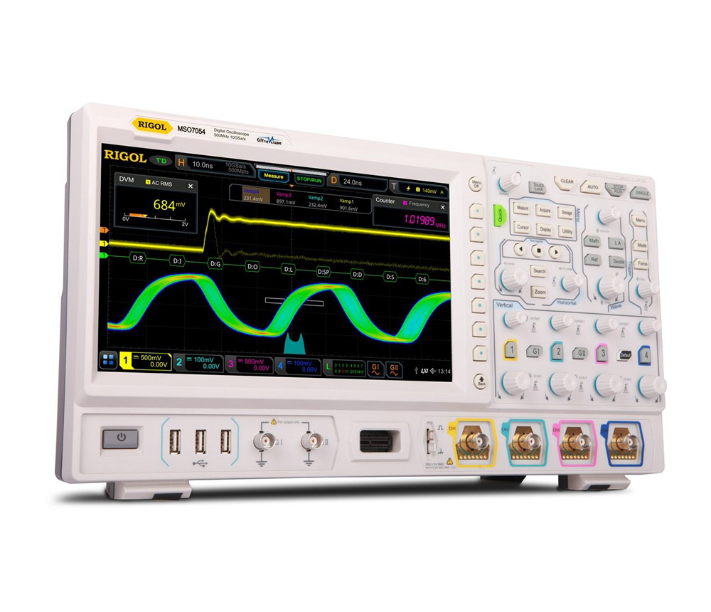
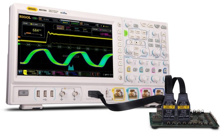
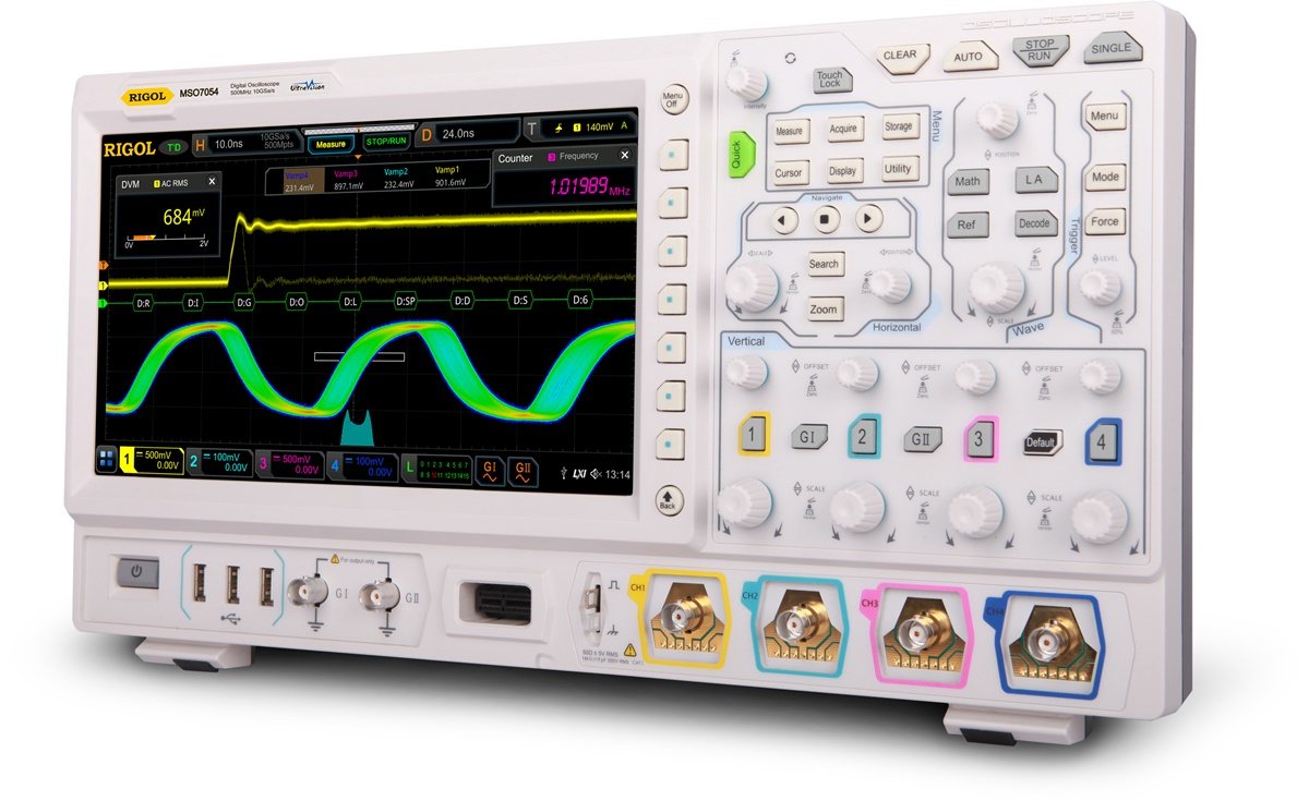
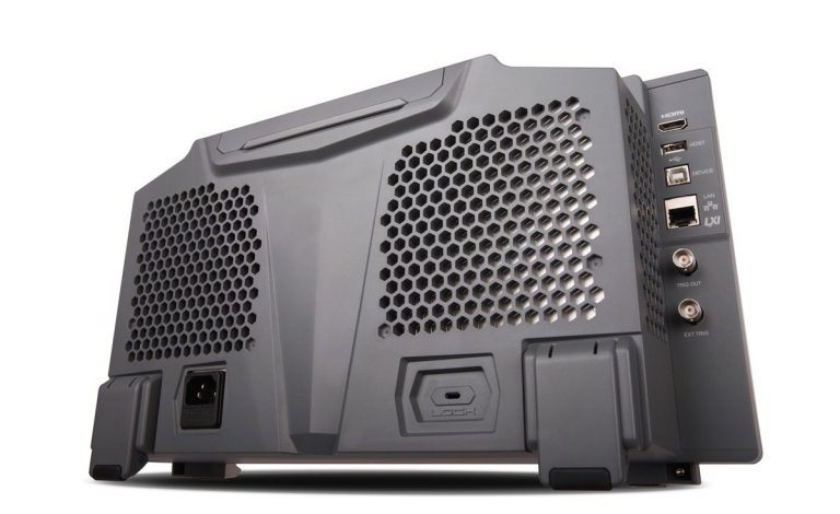
The RIGOL MSO7014 Mixed-Signal Oscilloscope is the 100 MHz model in the MSO7000 Series. It combines high-speed analogue acquisition, 16-channel digital logic analysis, protocol debugging and advanced waveform-analysis functions in one benchtop instrument.
The MSO7014 provides:
- Four analogue channels
- 100 MHz analogue bandwidth
- Sixteen digital channels
- Up to 10 GSa/s real-time sampling
- 100 Mpts standard single-channel memory
- Optional expansion to 500 Mpts
- More than 600,000 waveform captures per second
- Optional dual-channel 25 MHz waveform generator
- Full-memory hardware measurements
- Protocol triggering and decoding
- 10.1-inch capacitive touchscreen
The instrument uses RIGOL’s Phoenix platform and UltraVision II technology. It is designed for engineers who need long record length, fast acquisition and time-correlated analogue and digital measurements.
100 MHz Analogue Bandwidth
The MSO7014 provides 100 MHz analogue bandwidth across four analogue input channels.
It is suitable for:
- Microcontroller and embedded-system debugging
- FPGA and CPLD testing
- PWM and pulse measurements
- Power-supply testing
- Sensor and actuator analysis
- Analogue amplifier testing
- Automotive electronics
- Communication-interface troubleshooting
- Multi-channel timing measurements
- General electronics development
The bandwidth can be upgraded through RIGOL software options to 200 MHz, 350 MHz or 500 MHz, depending on the purchased licence.
Four Analogue Channels
The four analogue input channels allow users to monitor several related signals simultaneously.
Typical measurements include:
- Clock, data, enable and reset signals
- Input and output waveforms
- Voltage and current
- Multiple power rails
- Sensor signal and controller response
- Gate-drive and switching-node waveforms
- Reference and measured signals
- Multi-stage start-up sequences
- Phase and timing relationships
Four-channel acquisition is valuable when a fault affects several parts of a system or when signal relationships must be examined together.
Sixteen Digital Channels
The MSO7014 includes a 16-channel logic analyser interface.
Digital channels support:
- Microcontroller GPIO debugging
- FPGA and CPLD analysis
- Parallel bus testing
- Digital timing measurements
- Mixed analogue and digital correlation
- Logic-pattern triggering
- Protocol decoding using digital inputs
- Embedded control-system troubleshooting
The digital channels use a compatible RIGOL logic probe. RIGOL currently lists the RPL2316 16-channel logic probe for the MSO7000 platform.
High-Speed Real-Time Sampling
The MSO7014 provides a maximum real-time sample rate of 10 GSa/s.
Typical analogue sampling allocation is:
- 10 GSa/s with one channel active
- 5 GSa/s per channel with two channels active
- 2.5 GSa/s per channel with four channels active
This high sampling rate supports detailed observation of:
- Fast waveform edges
- Narrow pulses
- Ringing and overshoot
- Timing variation
- Switching transients
- Communication waveform quality
- Intermittent signal disturbances
The available sample rate depends on the number of enabled channels and acquisition configuration.
Deep Acquisition Memory
The MSO7014 provides 100 Mpts standard maximum memory depth in single-channel operation.
Standard memory allocation is:
- 100 Mpts with one active channel
- 50 Mpts per channel with two active channels
- 25 Mpts per channel with four active channels
The optional memory upgrade increases the maximum record length to:
- 500 Mpts with one active channel
- 250 Mpts per channel with two active channels
- 125 Mpts per channel with four active channels
Deep memory allows engineers to capture long signal sequences while maintaining a high sampling rate.
It is useful for:
- Long serial communication packets
- Power-supply start-up analysis
- Embedded-system timing sequences
- Long PWM records
- Intermittent fault investigation
- Automotive communication analysis
- Production monitoring
- Detailed waveform zooming
RIGOL identifies 100 Mpts as standard and 500 Mpts as optional.
Waveform Capture Above 600,000 wfms/s
The MSO7014 provides a waveform capture rate above 600,000 waveforms per second under specified acquisition conditions.
Fast acquisition improves the probability of finding:
- Rare glitches
- Runt pulses
- Timing violations
- Signal dropouts
- Unstable waveform edges
- Intermittent noise
- Communication errors
- Abnormal switching events
RIGOL’s intensity-graded and colour-persistence display helps distinguish frequent waveform activity from rare events.
Full-Memory Hardware Measurements
The MSO7014 performs measurements across the complete acquisition record rather than limiting analysis to the portion visible on the display.
The instrument supports:
- Full-record automatic measurements
- Forty-one waveform parameters
- Up to ten displayed measurements
- Measurement statistics
- Long-record waveform analysis
- Hardware-accelerated processing
This is useful when analysing long acquisitions containing many cycles or communication events.
Advanced Trigger Functions
The MSO7014 provides a broad trigger system for isolating specific signal conditions.
Available trigger categories include:
- Edge
- Pulse width
- Slope
- Video
- Pattern
- Duration
- Timeout
- Runt
- Window
- Delay
- Setup and hold
- Nth edge
- Serial bus triggers
These functions help engineers capture:
- Narrow pulses
- Missing transitions
- Setup and hold violations
- Logic-pattern events
- Abnormal voltage conditions
- Selected protocol messages
- Intermittent signal faults
Protocol Triggering and Decoding
The MSO7014 supports protocol triggering and decoding for embedded, automotive, audio and aerospace communication systems.
Available protocol options include:
- RS232/UART
- I2C
- SPI
- CAN
- LIN
- I2S
- FlexRay
- MIL-STD-1553
The oscilloscope can decode up to four serial buses simultaneously and display decoded data in waveform and event-table formats. Protocol options depend on the installed software licences.
Optional Two-Channel 25 MHz Waveform Generator
The MSO7014 can be upgraded with the MSO7000-AWG option.
The optional waveform generator provides:
- Two output channels
- 200 MSa/s generation sample rate
- 14-bit vertical resolution
- Up to 25 MHz sine-wave output
- Up to 15 MHz square or pulse output
- Up to 100 kHz ramp output
- Up to 10 MHz arbitrary waveform output
- Adjustable amplitude and DC offset
The waveform generator is not standard on the base MSO7014 and should be described as optional unless the licence is included in the supplied package.
Waveform Mathematics and FFT
The MSO7014 supports advanced waveform mathematics and frequency-domain analysis.
Available functions include:
- Addition
- Subtraction
- Multiplication
- Division
- User-defined mathematical functions
- FFT
- Digital filtering
- Reference waveform comparison
- Histogram analysis
- Measurement statistics
The FFT function supports up to 1 Mpts of data and provides colour-based frequency-domain display for identifying transient and intermittent frequency components.
Histogram Analysis
The oscilloscope provides:
- Horizontal waveform histograms
- Vertical waveform histograms
- Measurement histograms
Histogram analysis can be used to evaluate:
- Clock jitter
- Noise distribution
- Measurement variation
- Long-term signal stability
- Timing and amplitude abnormalities
This helps users identify signal behaviour that may not be obvious from a single waveform capture.
Mask and Pass/Fail Testing
The MSO7014 includes hardware pass/fail testing.
Users can:
- Create waveform masks
- Compare live signals against reference limits
- Count passed and failed acquisitions
- Monitor signals over long periods
- Support production-line testing
- Detect occasional waveform deviations
The function is suitable for repetitive validation, manufacturing inspection and long-duration signal monitoring.
Digital Voltmeter and Counter
The MSO7000 platform combines several measurement instruments in one unit, including:
- Digital oscilloscope
- Logic analyser
- Protocol analyser
- Optional waveform generator
- Digital voltmeter
- Frequency counter and totaliser
This integrated architecture reduces the need for separate instruments during general electronics and embedded-system testing.
Search and Navigation
Search and navigation tools help users locate selected events within long waveform records.
Search conditions can be used to find:
- Selected edges
- Pulse-width events
- Runt pulses
- Logic patterns
- Protocol conditions
- Timing abnormalities
This is particularly useful when working with the optional 500 Mpts record length.
10.1-Inch Capacitive Touchscreen
The MSO7014 includes:
- 10.1-inch capacitive multi-touch display
- 1024 × 600 resolution
- Gesture-based control
- Physical knobs and buttons
- Mouse support
- Intensity grading
- Colour persistence
- Multi-window waveform analysis
The instrument can be operated through the touchscreen, front-panel controls or compatible remote interfaces.
Connectivity and Remote Control
Connectivity includes:
- USB Host
- USB Device
- LAN
- LXI
- HDMI output
- AUX or trigger output
- Optional USB-to-GPIB connectivity
- Browser-based remote control
- PC control software
- SCPI programming support
These interfaces support waveform transfer, automated testing, remote laboratory operation and production-system integration.
Applications
The RIGOL MSO7014 is suitable for:
- Embedded-system development
- Microcontroller debugging
- FPGA and CPLD testing
- Mixed-signal circuit analysis
- Serial protocol debugging
- Power electronics testing
- Switching power-supply analysis
- Automotive electronics
- CAN and LIN testing
- Industrial control systems
- Audio bus analysis
- Aerospace bus testing
- Signal-integrity troubleshooting
- Production-line validation
- Research and development
- Engineering education