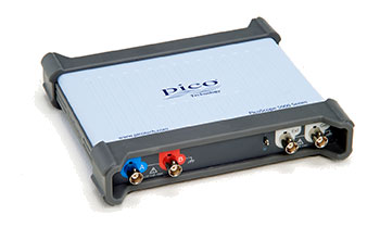
The PicoScope 5000D Series FlexRes USB Oscilloscope is designed for engineers, electronics developers, research teams, educational laboratories and production-test users who need both fast digital debugging and detailed analogue measurements.
Pico Technology’s FlexRes architecture allows the same oscilloscope to operate at different hardware resolutions. Users can select lower resolution for maximum sampling speed or higher resolution for improved vertical detail and lower-noise measurements.
The series provides:
- Two or four analogue input channels
- Optional 16 digital inputs on MSO models
- 60 MHz, 100 MHz or 200 MHz analogue bandwidth
- Selectable 8, 12, 14, 15 or 16-bit hardware resolution
- Up to 20-bit enhanced resolution
- Up to 1 GS/s sampling in 8-bit mode
- Up to 512 MS capture memory
- Up to 130,000 waveform captures per second
- Built-in 20 MHz function generator
- Built-in 14-bit arbitrary waveform generator
- Serial protocol decoding
- FFT spectrum analysis
- DeepMeasure analysis
- PicoScope software and PicoSDK support
This combination makes the PicoScope 5000D Series suitable for digital debugging, precision analogue testing, power-supply measurements, audio analysis, embedded development and automated test applications.
FlexRes Adjustable Hardware Resolution
The defining feature of the PicoScope 5000D Series is its selectable hardware resolution.
Available resolution modes include:
- 8 bits
- 12 bits
- 14 bits
- 15 bits
- 16 bits
The oscilloscope rearranges multiple analogue-to-digital converters to prioritise either sampling speed or vertical resolution.
Typical performance includes:
- 1 GS/s maximum sampling at 8-bit resolution
- 500 MS/s maximum sampling at 12-bit resolution
- 125 MS/s maximum sampling at 14-bit resolution
- 125 MS/s maximum sampling at 15-bit resolution
- 62.5 MS/s maximum sampling at 16-bit resolution
Enhanced-resolution processing can add up to four additional bits, providing up to 20-bit effective resolution under suitable acquisition conditions.
This flexibility allows engineers to use the same instrument for:
- Fast digital signal analysis
- Power-supply ripple measurement
- Low-noise analogue testing
- Sensor signal analysis
- Audio electronics
- Precision voltage measurement
- Switching waveform analysis
- Communication-interface debugging
60 MHz to 200 MHz Analogue Bandwidth
The PicoScope 5000D Series is available with:
- 60 MHz bandwidth
- 100 MHz bandwidth
- 200 MHz bandwidth
Model-dependent calculated rise times are:
- Approximately 5.8 ns at 60 MHz
- Approximately 3.5 ns at 100 MHz
- Approximately 1.75 ns at 200 MHz
In 16-bit mode, analogue bandwidth is limited to approximately 60 MHz, including on higher-bandwidth models.
Typical applications include:
- Microcontroller and FPGA debugging
- PWM and pulse measurement
- Sensor and actuator testing
- Switching power-supply analysis
- Analogue amplifier testing
- Audio circuit analysis
- Clock and timing measurement
- Communication physical-layer testing
- Power-rail ripple and noise analysis
- General electronics development
Two-Channel and Four-Channel Models
The range includes both two-channel and four-channel configurations.
Two-channel models are suitable for:
- Input and output comparison
- Voltage and current analysis
- Clock and data testing
- Sensor and controller correlation
- Phase and delay measurement
Four-channel models support:
- Multiple power-rail measurement
- Clock, data, enable and reset analysis
- Multi-stage power-converter testing
- High-side and low-side gate-drive analysis
- Input voltage, input current, output voltage and output current
- Multi-signal timing measurements
All enabled analogue channels are sampled simultaneously, preserving time relationships between signals.
PicoScope 5000D Model Range
| Model |
Analogue Channels |
Digital Channels |
Bandwidth |
Maximum 8-Bit Memory |
| PicoScope 5242D |
2 |
None |
60 MHz |
128 MS |
| PicoScope 5242D MSO |
2 |
16 |
60 MHz |
128 MS |
| PicoScope 5442D |
4 |
None |
60 MHz |
128 MS |
| PicoScope 5442D MSO |
4 |
16 |
60 MHz |
128 MS |
| PicoScope 5243D |
2 |
None |
100 MHz |
256 MS |
| PicoScope 5243D MSO |
2 |
16 |
100 MHz |
256 MS |
| PicoScope 5443D |
4 |
None |
100 MHz |
256 MS |
| PicoScope 5443D MSO |
4 |
16 |
100 MHz |
256 MS |
| PicoScope 5244D |
2 |
None |
200 MHz |
512 MS |
| PicoScope 5244D MSO |
2 |
16 |
200 MHz |
512 MS |
| PicoScope 5444D |
4 |
None |
200 MHz |
512 MS |
| PicoScope 5444D MSO |
4 |
16 |
200 MHz |
512 MS |
Up to 1 GS/s Real-Time Sampling
Sampling performance depends on hardware resolution and the number of active acquisition channels.
In 8-bit mode:
- One active channel: up to 1 GS/s
- Two active channels: up to 500 MS/s
- Three or four active channels: up to 250 MS/s
- More than four acquisition resources: up to 125 MS/s
In 12-bit mode:
- One active channel: up to 500 MS/s
- Two active channels: up to 250 MS/s
- Three or four active channels: up to 125 MS/s
- More than four resources: up to 62.5 MS/s
In 14-bit mode:
- Up to 125 MS/s with one to four channels
- Up to 62.5 MS/s with more than four acquisition resources
In 16-bit mode:
One eight-channel digital port on an MSO model counts as one acquisition resource when calculating the available sampling rate.
Equivalent-Time Sampling
For stable repetitive signals, equivalent-time sampling can provide effective sampling rates up to:
- 2.5 GS/s on 60 MHz models
- 5 GS/s on 100 MHz models
- 10 GS/s on 200 MHz models
Equivalent-time sampling combines several repetitive acquisitions and should not be presented as the real-time sampling rate for single-shot signals.
Deep Capture Memory
Capture memory depends on the selected model and resolution.
In 8-bit mode:
- 128 MS on x242D models
- 256 MS on x243D models
- 512 MS on x244D models
At 12-bit resolution and above:
- 64 MS on x242D models
- 128 MS on x243D models
- 256 MS on x244D models
Memory is shared between enabled analogue channels and digital ports.
Deep memory supports:
- Long serial communication captures
- High-resolution waveform zoom
- Power-supply start-up analysis
- Long PWM records
- Intermittent fault investigation
- Audio waveform analysis
- Production-test monitoring
- Extended data acquisition
The PicoScope 5000D Series can retain high sampling rates over considerably longer time intervals than oscilloscopes with smaller memory.
Segmented Memory and Rapid Triggering
The capture memory can be divided into individual waveform segments.
PicoScope software supports up to:
PicoSDK supports up to:
- 250,000 segments on x242D models in 8-bit mode
- 500,000 segments on x243D models in 8-bit mode
- 1,000,000 segments on x244D models in 8-bit mode
Segmented acquisition helps record important events without filling memory with inactive periods.
It is useful for:
- Serial communication packets
- Switching pulses
- Injector or ignition events
- Rare glitches
- Repetitive production tests
- Intermittent trigger conditions
Trigger rearm time can be approximately 1 µs under specified conditions.
Up to 130,000 Waveforms per Second
The PicoScope 5000D Series supports waveform capture rates up to approximately 130,000 wfms/s.
Fast acquisition improves the probability of detecting:
- Rare glitches
- Runt pulses
- Timing violations
- Signal dropouts
- Unstable waveform edges
- Switching disturbances
- Communication errors
- Intermittent noise
Actual waveform update performance depends on the selected acquisition mode, host computer and display configuration.
Sixteen Digital Inputs on MSO Models
PicoScope 5000D MSO models include 16 digital inputs arranged into two groups:
Digital input capabilities include:
- Maximum input frequency of 100 MHz
- Data rates up to approximately 200 Mb/s
- Minimum detectable pulse width of 5 ns
- ±20 V input range
- ±5 V adjustable threshold range
- Two independent logic-threshold controls
- TTL, CMOS, ECL and PECL threshold presets
- Mixed analogue and digital triggering
Digital inputs can be displayed individually or organised into binary, decimal or hexadecimal buses.
They are suitable for:
- Microcontroller GPIO debugging
- FPGA and CPLD testing
- Parallel bus analysis
- Digital timing measurements
- Serial protocol decoding
- Mixed analogue and digital system analysis
Only models carrying the MSO designation include the digital inputs.
Serial Protocol Decoding
PicoScope software includes serial decoding without requiring separate protocol licences.
Supported protocols include common embedded, automotive, industrial, audio and communication buses such as:
- I²C
- SPI
- UART and RS232
- CAN
- LIN
- FlexRay
- I²S
- USB
- Modbus
- SENT
- Manchester
- Parallel bus
Decoded information can be displayed:
- Directly below the waveform
- In a protocol table
- In hexadecimal, binary, decimal or ASCII format
- Across multiple stored waveform buffers
MSO models can use both analogue and digital channels as protocol sources.
Advanced Digital Triggering
The PicoScope 5000D Series uses digitised waveform data for accurate trigger detection.
Trigger types include:
- Edge
- Window
- Pulse width
- Window pulse width
- Dropout
- Window dropout
- Interval
- Runt pulse
- Logic
- Digital pattern
- Mixed analogue and digital conditions
These triggers help isolate:
- Narrow pulses
- Missing transitions
- Abnormal pulse widths
- Logic-pattern conditions
- Voltage dropouts
- Intermittent faults
- Communication errors
MSO models can trigger on any selected combination of analogue and digital inputs.
Built-In 20 MHz Function Generator
Every PicoScope 5000D model includes a built-in function generator.
Standard waveforms include:
- Sine
- Square
- Triangle
- DC
- Ramp up
- Ramp down
- Sinc
- Gaussian
- Half-sine
- White noise
- Pseudorandom binary sequence
The generator provides:
- Frequency range from 0.025 Hz to 20 MHz
- Adjustable amplitude
- Adjustable DC offset
- Frequency sweeps
- Triggered operation
- PRBS output up to 20 Mb/s
Typical applications include:
- Amplifier testing
- Filter evaluation
- Sensor simulation
- Circuit stimulus generation
- Frequency-response testing
- Educational experiments
- Production validation
Built-In 14-Bit Arbitrary Waveform Generator
The integrated arbitrary waveform generator provides:
- 14-bit output resolution
- 200 MS/s update rate
- 32 kS waveform memory
- More than 20 MHz analogue bandwidth
- Rise time below 10 ns with a 50 Ω load
Users can:
- Draw custom waveforms
- Import waveform data
- Replay previously acquired signals
- Generate application-specific test patterns
- Create stimulus signals for circuit validation
The AWG is included across the PicoScope 5000D Series and should not be described as an optional licence.
Low-Level Signal Measurement
The analogue input system provides full-scale ranges from:
Input sensitivity ranges from:
The input system includes:
- 1 MΩ input impedance
- AC or DC coupling
- Selectable 20 MHz bandwidth limit
- Analogue offset control
- ±100 V overvoltage protection
Higher-resolution modes support detailed measurements of:
- Power-supply ripple
- Sensor output
- Audio signals
- Amplifier distortion
- Reference-voltage stability
- Low-noise analogue circuits
Typical input noise on the ±10 mV range falls from approximately 120 µV RMS in 8-bit mode to around 70 µV RMS in 16-bit mode.
DeepMeasure Analysis
DeepMeasure automatically analyses individual waveform cycles within long acquisitions.
It can provide cycle-by-cycle results for:
- Frequency
- Period
- Pulse width
- Rise time
- Fall time
- Duty cycle
- Maximum voltage
- Minimum voltage
- Amplitude
- Timing variation
Results can be sorted and correlated with the waveform to locate individual abnormal events.
This is useful for:
- Clock stability analysis
- PWM testing
- Long-term timing measurements
- Production validation
- Intermittent fault detection
FFT Spectrum Analysis
PicoScope software includes FFT-based spectrum analysis with a frequency range extending to the selected oscilloscope bandwidth.
It supports:
- Multiple FFT window functions
- Average and peak-hold modes
- Harmonic measurement
- Noise analysis
- Frequency markers
- Spectrum masks
- Distortion measurements
- Multiple spectrum views
Typical applications include:
- Harmonic analysis
- Amplifier testing
- Switching-frequency measurement
- Audio testing
- Noise-source identification
- Detection of unwanted oscillations
The highest-bandwidth model supports spectrum analysis up to approximately 200 MHz.
Mask Limit Testing
Mask testing compares acquired waveforms against a known-good reference envelope.
Users can:
- Automatically create masks
- Count passed and failed acquisitions
- Search waveform buffers for failures
- Save failed waveforms
- Trigger automated actions
- Stop acquisition when a violation occurs
Mask testing supports:
- Production-line inspection
- Repetitive quality testing
- Signal-stability monitoring
- Component comparison
- Long-duration fault detection
PicoScope Software
PicoScope software provides:
- Oscilloscope views
- Spectrum analysis
- Serial decoding
- Automatic measurements
- Waveform mathematics
- Mask testing
- DeepMeasure
- Reference waveforms
- Multiple waveform views
- Custom probe scaling
- Waveform buffer navigation
- Automated actions
The large computer display allows several oscilloscope and spectrum views to be shown simultaneously.
PicoScope software is available without recurring licence charges.
PicoSDK and Automated Test Integration
PicoSDK allows direct control of the instrument from custom software.
It supports applications such as:
- Automated production testing
- Research data acquisition
- Long-duration monitoring
- OEM integration
- Custom user interfaces
- Laboratory automation
- Continuous USB streaming
Maximum continuous USB streaming performance can reach:
- Up to 125 MS/s in 8-bit mode
- Up to 62.5 MS/s in 12 to 16-bit modes
Actual streaming speed depends on the computer, USB interface and software configuration.
Compact USB 3.0 Design
The PicoScope 5000D Series connects to a host computer through USB 3.0.
Benefits include:
- Compact desktop footprint
- Portable laptop-based operation
- Direct waveform storage
- Large computer-based display
- Easy report creation
- Remote software control
- Integration into automated test systems
- Silent fanless operation
Four-channel models and some operating configurations may require the supplied external power adaptor.
Applications
The PicoScope 5000D Series is suitable for:
- Embedded-system development
- Microcontroller debugging
- FPGA and CPLD testing
- Mixed-signal circuit analysis
- Precision analogue measurement
- Power-supply ripple testing
- Audio and amplifier analysis
- Power electronics
- Serial protocol debugging
- PWM and pulse measurement
- Automotive electronics
- Sensor and actuator testing
- Research and development
- Production-line testing
- Engineering education
- Electronic service and repair
- OEM integration
- Automated test systems