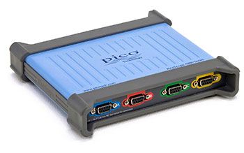
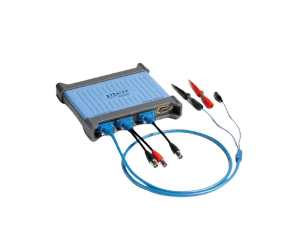
The PicoScope 4444 High-Resolution Differential Oscilloscope is designed for engineers who need to measure voltage or current at different circuit reference points without connecting every channel to a shared oscilloscope ground.
It combines:
- Four true differential input channels
- 20 MHz maximum analogue bandwidth
- Selectable 12-bit and 14-bit hardware resolution
- Up to 18-bit enhanced resolution
- Up to 400 MS/s real-time sampling
- 256 MS shared capture memory
- High common-mode rejection
- ±50 V differential and common-mode input range
- 1000 V CAT III measurement capability with the PicoConnect 442 probe
- PicoScope 7 software
- PicoSDK support for automated testing
The four Pico D9 inputs accept compatible differential voltage probes, current probes and D9-to-BNC adaptors. This flexible input system makes the instrument suitable for power, energy, industrial, automotive and precision electronic measurements.
Four True Differential Inputs
Each input measures the voltage difference between two points rather than measuring one point relative to the computer or oscilloscope ground.
This allows engineers to measure:
- High-side and low-side switching signals
- Floating power-supply outputs
- Voltage across current-sense resistors
- Three-phase motor and inverter signals
- Differential communication lines
- Bridge circuits
- Non-ground-referenced sensor outputs
- Multiple signals with different reference potentials
True differential inputs also reduce the risk of creating unwanted ground loops when several channels are connected to different parts of a system.
High Common-Mode Rejection
The PicoScope 4444 is designed to reject voltage that is common to both sides of a differential input while displaying the smaller voltage difference between them.
This is useful when measuring:
- Small ripple on a high DC voltage
- Current-shunt voltage in a switching circuit
- Gate-drive signals on floating power stages
- Differential sensor outputs
- Noise-sensitive analogue circuits
- Power-converter input and output signals
The oscilloscope provides typical crosstalk performance of 2000:1 from DC to the applicable analogue bandwidth.
Selectable 12-Bit and 14-Bit Resolution
The PicoScope 4444 supports two hardware-resolution modes:
- 12-bit mode for higher real-time sampling rates
- 14-bit mode for greater vertical detail
A 12-bit acquisition provides 4,096 quantisation levels, while a 14-bit acquisition provides 16,384 levels.
Enhanced-resolution processing can increase effective resolution to:
- Up to 16 bits from 12-bit mode
- Up to 18 bits from 14-bit mode
This makes the oscilloscope suitable for measurements where small waveform details must be separated from larger signal levels.
Typical high-resolution applications include:
- Power-supply ripple
- Current-shunt voltage
- Battery current analysis
- Low-noise sensor signals
- Audio and instrumentation circuits
- Power-conversion efficiency testing
- Harmonic measurement
- Small AC signals riding on DC voltages
Up to 20 MHz Analogue Bandwidth
Bandwidth depends on the connected probe or adaptor:
- Up to 20 MHz with compatible D9-to-BNC adaptors
- Up to 15 MHz with the PicoConnect 441 differential voltage probe
- Up to 10 MHz with the PicoConnect 442 1000 V CAT III probe
Calculated rise time is:
- Approximately 17.5 ns with a D9-to-BNC adaptor
- Approximately 23 ns with the PicoConnect 441
- Approximately 35 ns with the PicoConnect 442
The connected probe should therefore be considered when publishing or comparing bandwidth performance.
Up to 400 MS/s Real-Time Sampling
In 12-bit mode, maximum sampling depends on the number of enabled channels:
- 400 MS/s with one active channel
- 200 MS/s per channel with two active channels
- 100 MS/s per channel with three or four active channels
In 14-bit mode, the maximum real-time sampling rate is 50 MS/s.
This flexibility allows users to prioritise sampling speed or vertical resolution according to the measurement.
256 MS Deep Capture Memory
The PicoScope 4444 provides 256 MS capture memory, shared between enabled channels.
Deep memory allows users to:
- Capture long start-up events
- Maintain useful sampling rates on slower time bases
- Record switching sequences
- Analyse power-cycle behaviour
- Investigate intermittent faults
- Zoom into individual waveform events
- Compare many cycles
- Capture long serial communication records
USB streaming mode supports up to 100 MS of shared memory, while block acquisition uses the full 256 MS memory.
Up to 40,000 Waveform Buffers
PicoScope software can retain up to 40,000 waveform acquisitions in its waveform buffer.
Users can:
- Review previous captures
- Compare normal and abnormal events
- Search for mask violations
- Examine intermittent faults
- Apply measurements to stored waveforms
- Navigate through rapid-trigger captures
This is useful when an abnormal waveform appears briefly and disappears before acquisition is manually stopped.
Wide Differential Input Range
Without an external differential probe, the PicoScope 4444 supports full-scale differential input ranges from approximately:
The maximum common-mode range is also ±50 V when using the compatible direct-input configuration.
These ranges support:
- Millivolt-level shunt measurements
- Sensor outputs
- Power-supply rails
- Battery systems
- Industrial control signals
- General power electronics
Input range and safety rating change according to the attached probe or adaptor.
1000 V CAT III Measurements
When used with the PicoConnect 442 25:1 passive differential voltage probe, the PicoScope 4444 can measure up to:
- ±1000 V differential voltage
- ±1000 V common-mode voltage
- 1000 V CAT III environments
This configuration is suitable for:
- Mains voltage
- Power distribution
- Motor drives
- Inverters
- UPS systems
- Industrial power equipment
- Hybrid and electric vehicle high-voltage systems
- Battery packs
- Chargers and converters
The PicoConnect 442 configuration has 10 MHz bandwidth.
Differential Voltage Measurement with PicoConnect 441
The PicoConnect 441 is a passive differential voltage probe intended for lower-voltage measurements.
It supports applications such as:
- Non-ground-referenced power rails
- Differential sensor outputs
- Current-shunt measurements
- Control electronics
- Audio and instrumentation circuits
- Low-voltage power-conversion testing
With this probe, the oscilloscope provides up to 15 MHz analogue bandwidth.
Current Measurement
Compatible Pico current probes can be connected directly to the Pico D9 inputs.
Depending on the selected probe, the PicoScope 4444 can support:
- Low-current electronic measurements
- Battery current
- Inrush current
- Motor current
- Three-phase current
- Power-converter current
- Current up to 2000 A with compatible probes
This allows voltage and current to be captured together for power, efficiency and phase analysis.
Power Electronics Testing
The PicoScope 4444 is particularly suited to power-conversion measurements because all four channels are differential.
Typical measurements include:
- Input voltage and current
- Output voltage and current
- Gate-drive signals
- Switching-node voltage
- Current-shunt signals
- Converter start-up
- Efficiency calculations
- Power factor
- Harmonic behaviour
- Switching losses
- Ripple and noise
Four differential channels allow multiple floating measurements without using several separate differential probe amplifiers.
Three-Phase Power Measurements
The four-channel architecture can support three-phase voltage or current analysis with suitable probes.
Applications include:
- Three-phase motor drives
- Industrial inverters
- Variable-frequency drives
- Motor phase-current analysis
- Phase-voltage comparison
- Power quality investigation
- Industrial energy systems
Probe selection depends on the maximum voltage, current, measurement category and bandwidth required.
Hybrid and Electric Vehicle Testing
With suitable PicoConnect voltage and current probes, the PicoScope 4444 can be used for:
- High-voltage battery testing
- Inverter input and output analysis
- Motor phase measurements
- Charger testing
- DC-to-DC converter testing
- Current consumption
- Isolation-related diagnostics
- Power-electronics troubleshooting
Pico Technology identifies hybrid and electric vehicle systems as a major application area for the 4444 and its 1000 V CAT III accessories.
Low-Noise Measurement Performance
The high-resolution architecture provides typical noise below:
- 180 µV RMS on the ±10 mV input range
The oscilloscope also provides:
- Greater than 70 dB spurious-free dynamic range
- Approximately 10.8 effective bits in 12-bit mode
- Approximately 11.8 effective bits in 14-bit mode
These specifications support precision measurements where signal fidelity is more important than very high analogue bandwidth.
Switchable Bandwidth Limits
Selectable bandwidth limits include:
- 100 kHz
- 1 MHz
- Full available probe bandwidth
Bandwidth limiting helps reduce unwanted high-frequency noise during:
- Power-supply ripple measurement
- Low-frequency current testing
- Sensor measurements
- Battery-current analysis
- Control-loop testing
- Audio and instrumentation work
Simultaneous Sampling
All enabled channels are sampled simultaneously.
This helps maintain accurate time relationships between:
- Voltage and current
- Input and output power
- Motor phases
- Gate-drive and switching waveforms
- Sensor and control signals
- Multiple power rails
Simultaneous sampling is particularly important for phase, timing and power calculations.
Advanced Triggering
PicoScope software supports multiple trigger types, including:
- Edge
- Window
- Pulse width
- Window pulse width
- Dropout
- Window dropout
- Interval
- Logic
- Runt pulse
These trigger modes help isolate:
- Short switching pulses
- Missing cycles
- Voltage dropouts
- Timing faults
- Unstable power events
- Intermittent circuit behaviour
- Abnormal current pulses
Automatic Measurements
PicoScope 7 provides automatic voltage, timing and frequency measurements.
Typical measurements include:
- Maximum and minimum voltage
- Peak-to-peak voltage
- Average voltage
- RMS voltage
- Frequency
- Period
- Rise and fall time
- Pulse width
- Duty cycle
- Phase
- Delay
Power-related maths and measurement functions can also be created using voltage and current channels.
FFT Spectrum Analysis
PicoScope 7 includes an FFT spectrum analyser for frequency-domain measurements.
It can support:
- Harmonic analysis
- Switching-frequency measurement
- Power-supply noise analysis
- Motor-drive spectral analysis
- EMI troubleshooting
- Audio measurements
- Identification of unwanted oscillations
Spectrum and oscilloscope views can be displayed together for time-domain and frequency-domain comparison.
Waveform Mathematics
Available maths functions include:
- Addition
- Subtraction
- Multiplication
- Division
- Integration
- Differentiation
- Filtering
- RMS calculations
- Frequency calculations
- User-defined equations
Multiplying voltage and current channels can support instantaneous power analysis.
Mask Limit Testing
Mask testing compares live waveform data against a defined reference envelope.
It can be used for:
- Production validation
- Power-supply consistency testing
- Component comparison
- Repetitive quality checks
- Long-duration monitoring
- Detection of intermittent waveform deviations
The waveform buffer can be searched to identify captures that fail the mask.
PicoScope 7 Software
PicoScope 7 provides:
- Oscilloscope views
- Spectrum views
- Automatic measurements
- Waveform mathematics
- Mask testing
- Reference waveforms
- Serial decoding
- Multiple views
- Waveform buffer navigation
- Custom probe scaling
- Automated actions
PicoScope software is available for Windows, macOS and Linux.
PicoSDK and Automated Testing
PicoSDK allows the PicoScope 4444 to be integrated into custom software and automated test systems.
It can support:
- Production testing
- Power-converter validation
- Research equipment
- Long-duration monitoring
- Custom data acquisition
- OEM test systems
- Laboratory automation
- Bespoke user interfaces
The PicoScope 4000 Series A API programmer’s guide is available through Pico Technology’s official documentation library.
USB-Connected PC Oscilloscope
The PicoScope 4444 uses a computer as its display and control interface.
Benefits include:
- Large waveform viewing area
- Flexible multi-window layouts
- Easy report creation
- Direct file storage
- Remote software control
- Simple waveform export
- Compact hardware footprint
- No separate oscilloscope display required
The oscilloscope connects through USB 3.0 and is supplied with an external power adaptor.
Applications
The PicoScope 4444 is suitable for:
- Power electronics development
- Switched-mode power supplies
- Motor drives and inverters
- Three-phase power systems
- Mains measurement
- Hybrid and electric vehicles
- Battery systems
- Charger testing
- Current-shunt measurement
- Differential sensor testing
- Energy-efficiency analysis
- Power quality investigation
- Low-noise analogue measurements
- Industrial control systems
- Research and development
- Automated production testing
- Engineering education
Why Buy from RevineTech?
RevineTech supplies Pico Technology oscilloscopes, differential probes and current-measurement accessories for power electronics, automotive, industrial and research applications.
Technical product-selection support can include:
- PicoScope 4444 configuration
- PicoConnect 441 probe selection
- PicoConnect 442 high-voltage probe selection
- Current probe selection
- Single-phase and three-phase measurement kits
- Hybrid and EV testing accessories
- D9-to-BNC adaptors
- Calibration documentation
- PicoSDK integration
- Automated test-system development