Home Cleverscope | Oscilloscopes Cleverscope Trigger and Protocol Analysis System
Cleverscope | Oscilloscopes

Cleverscope Trigger and Protocol Analysis System

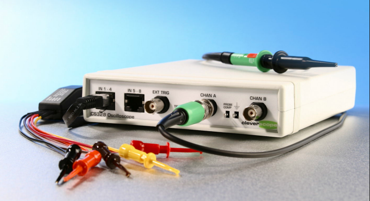
The Cleverscope system provides powerful dual-trigger capabilities and built-in protocol decoding for analyzing SPI, UART, and other serial data signals. Designed for engineers testing timing relationships and communication sequences in embedded systems..

  • Detail
  • Special Features
  • Specification

The Cleverscope system allows users to set two separate triggers with configurable edge direction (rising/falling), source channel, voltage threshold, and noise filters. Triggers can be logically combined using timing constraints (Trig1~2 < min, > max, or between min and max), or with event counting (e.g., “Trigger if Trigger 2 occurs 8 times after Trig1”).

The protocol decoding engine supports:

  • SPI: Setup includes clock, data, and chip select inputs

  • UART (TxD): Setup via analog or digital sources with selectable baud rate

Captured data can be decoded and exported using Notes, which are formatted with tab characters for direct Excel usage. The Get Frame button boosts sample transfer for full-resolution decoding, overcoming display buffer limitations.

Use cases demonstrated include validating SPI timing (e.g., CS* to CLK delay) and monitoring frequency-setting messages via UART. Engineers can use the dual-trigger logic to identify and isolate subtle timing violations across system conditions.

  • Dual independent trigger systems (Trigger 1 & 2)

  • Combined trigger logic with duration, count, or OR conditions

  • Supports analog and digital signal sources including SPI/UART

  • Digital input pattern filters for precise triggering

  • Built-in protocol decoders with SPI and UART support

  • “Get Frame” for full-resolution decoding (10ns)

  • Copy to Notes for easy documentation and Excel export

  • Deep memory capture (4 Mega samples) for long-time zoom

Parameter Details
Trigger Sources Chan A, Chan B, Ext Trigger, Link Input, Digital Inputs (1–8)
Trigger Types Rising, Falling, Digital Pattern Match
Trigger Filters None, Low Pass, High Pass, Noise
Trigger Combinations Time-based, Count-based, OR logic, Trig1~2 duration
Trigger Timing Accuracy 10 ns resolution
Digital Input Pattern Options High (1), Low (0), Don’t Care (X), Edge-triggered
Protocol Support SPI, UART/TxD (ASCII)
Baud Rate Range (UART) User-selectable via drop-down
Buffer Depth 4 Mega samples
Protocol Decoding Display Excel/Notes export with timestamps and signal values
Minimum Setup Time Detected Down to ±50 ns precision for trigger validation
Example Use Case SPI chip-select to clock edge validation, frequency control monitoring