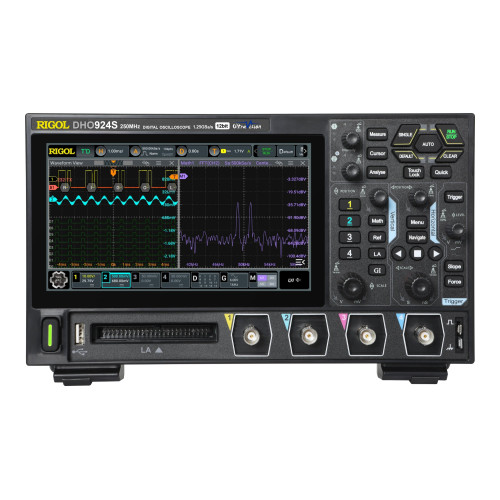
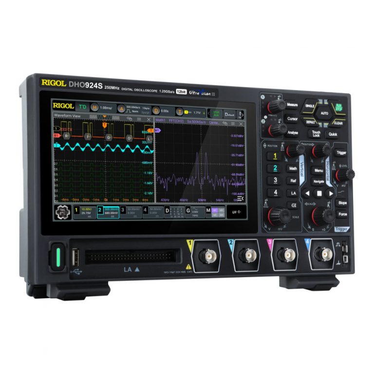
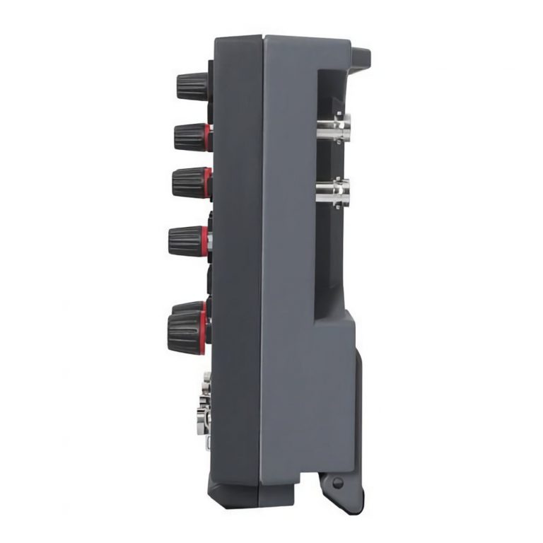
The RIGOL DHO914S Digital Oscilloscope combines high-resolution waveform acquisition, signal generation and mixed-signal analysis in a compact test platform. It is designed for embedded-system development, power electronics, automotive testing, analogue circuit analysis, education and production validation.
The instrument provides:
- Four analogue channels
- 125 MHz analogue bandwidth
- Native 12-bit vertical resolution
- Up to 1.25 GSa/s real-time sampling
- Up to 50 Mpts memory depth
- UltraAcquire capture up to 1,000,000 wfms/s
- A built-in single-channel 25 MHz AFG
- Bode plot analysis
- Support for 16 digital channels with the optional PLA2216 probe
- A 7-inch capacitive touchscreen
The DHO914S is based on RIGOL’s Centaurus platform. Its 12-bit analogue-to-digital converter provides 4,096 vertical quantisation levels, which is 16 times the number provided by an 8-bit acquisition system. This helps reveal small changes in ripple, noise, overshoot and signal amplitude.
125 MHz Analogue Bandwidth
The DHO914S provides 125 MHz bandwidth across four analogue input channels and a typical rise time of 2.8 ns or less.
It is suitable for:
- Microcontroller and FPGA debugging
- PWM and control-signal analysis
- Switching power-supply testing
- Sensor and actuator measurements
- Analogue amplifier testing
- Power-rail ripple analysis
- Automotive electronics
- Communication-interface testing
- Timing and phase measurements
- General electronics troubleshooting
Measurement performance also depends on probe bandwidth, connection quality, source impedance and grounding.
Native 12-Bit Resolution
The native 12-bit acquisition system supports:
- 4,096 vertical quantisation levels
- Improved low-amplitude signal visibility
- Better ripple and noise analysis
- More detailed waveform representation
- Improved measurement of small signals on DC rails
- Clearer identification of overshoot and distortion
This makes the oscilloscope useful for power integrity, sensor testing, audio electronics, low-noise analogue design and battery-management systems.
Four Analogue Channels
The four analogue channels allow engineers to analyse several related signals simultaneously, including:
- Clock, data and enable signals
- Voltage and current waveforms
- Converter input and output signals
- Multiple power rails
- Gate-drive and switching-node signals
- Sensor output and controller response
- Reference and measured waveforms
- Multi-stage start-up sequences
-
Channel-Dependent Sampling Rate
Maximum real-time sampling depends on the number of active analogue channels:
- One active channel: 1.25 GSa/s
- Two active channels: 625 MSa/s per channel
- Three or four active channels: 312.5 MSa/s per channel
The active-channel configuration should be considered when capturing faster waveforms.
Deep Acquisition Memory
The DHO914S provides up to 50 Mpts acquisition memory.
Memory allocation is:
- 50 Mpts with one active channel
- 25 Mpts per channel with two active channels
- 10 Mpts per channel with three or four active channels
Deep memory supports longer captures for:
- Serial communication packets
- Power-supply start-up testing
- PWM and control sequences
- Long pulse trains
- Intermittent fault investigation
- Motor-control analysis
- Embedded timing measurements
- Production validation
-
UltraAcquire Waveform Capture
UltraAcquire mode provides waveform capture rates up to 1,000,000 waveforms per second. Standard vector-mode acquisition reaches up to 30,000 wfms/s.
Fast acquisition helps detect:
- Rare glitches
- Runt pulses
- Timing violations
- Signal dropouts
- Unstable waveform edges
- Intermittent communication faults
- Abnormal switching behaviour
- Power disturbances
-
Hardware Waveform Recording
The DHO914S supports hardware waveform recording and playback for up to 500,000 frames.
Engineers can:
- Record successive waveform events
- Replay captures frame by frame
- Compare normal and abnormal signals
- Perform measurements during playback
- Review decoded bus activity
- Investigate intermittent faults
- Identify events preceding a failure
-
Built-In Single-Channel 25 MHz AFG
The DHO914S includes a single-channel 25 MHz function/arbitrary waveform generator as standard.
It can produce:
- Sine waveforms
- Square waveforms
- Ramp waveforms
- DC output
- Noise
- Arbitrary waveforms
The maximum sine-wave frequency is 25 MHz, while square-wave generation reaches up to 15 MHz. The AFG can be controlled directly from the oscilloscope or through supported remote commands.
Typical AFG applications include:
- Amplifier testing
- Filter evaluation
- Sensor simulation
- Clock and stimulus generation
- Component testing
- Circuit-response measurements
- Educational experiments
- Control-loop testing
-
Bode Plot Analysis
Bode plot analysis is standard on the DHO914S and DHO924S models. The oscilloscope uses its internal AFG to sweep a circuit across a selected frequency range and measures gain and phase response.
It supports:
- Linear or logarithmic frequency sweeps
- Start frequencies from 10 Hz
- Stop frequencies up to 25 MHz
- Adjustable sweep points
- Gain-response measurement
- Phase-response measurement
- Control-loop stability analysis
This function is useful for:
- Power-supply loop-response testing
- Filter characterisation
- Amplifier frequency-response analysis
- Gain and phase margin evaluation
- Feedback-system validation
Bode plot commands and operation are specifically available on the DHO914S and DHO924S.
Optional 16-Channel Logic Analysis
The DHO914S supports up to 16 digital channels using the optional PLA2216 logic analyser probe.
Digital analysis is suitable for:
- Microcontroller GPIO debugging
- FPGA and CPLD testing
- Parallel bus analysis
- Clock and data timing
- Mixed analogue and digital debugging
- Digital control-system testing
The digital interface is built into the oscilloscope, but the PLA2216 probe is sold separately.
Serial and Parallel Bus Analysis
The oscilloscope supports triggering and decoding for:
- RS232/UART
- I2C
- SPI
- CAN
- LIN
- Parallel buses
Bus sources can use analogue channels or digital channels when the logic probe is connected.
Protocol analysis helps locate:
- Incorrect data
- Missing acknowledgements
- Timing errors
- Communication interruptions
- Noise-related errors
- Voltage-level problems
- Physical-layer faults
-
Low-Level Signal Measurement
The DHO914S provides vertical sensitivity from 200 µV/div to 10 V/div.
This range supports:
- Power-rail ripple testing
- Sensor output measurements
- Reference-voltage analysis
- Low-noise amplifier testing
- Small analogue signals
- Converter output-noise measurements
The 200 µV/div and 500 µV/div settings use digital magnification from the 1 mV/div range.
Automatic Measurements and Analysis
Available analysis functions include:
- Voltage and timing measurements
- Frequency and period measurements
- Rise and fall time
- Pulse-width and duty-cycle measurements
- Phase and delay
- Measurement statistics
- Cursor measurements
- FFT analysis
- Waveform mathematics
- Digital filtering
- Histogram analysis
- Mask testing
- Search and navigation
- Reference waveform comparison
-
Display and Remote Operation
The instrument includes:
- 7-inch capacitive touchscreen
- 1024 × 600 resolution
- 256 intensity levels
- Multi-touch operation
- Flex Knob control
- HDMI external display output
- Web-based remote control
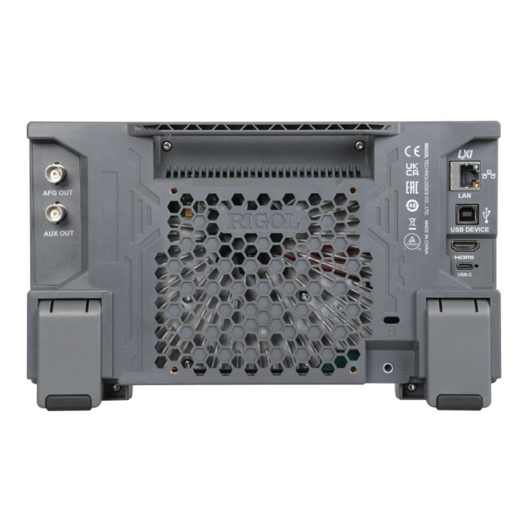
Connectivity includes USB Host, USB Device, LAN, LXI-C, HDMI and AUX output.
USB Type-C Power
The DHO914S uses a USB Type-C power input, supporting portable operation with a compatible power source.
This is useful for:
- Automotive field testing
- Industrial maintenance
- Mobile laboratory work
- Remote equipment inspection
- On-site electronics troubleshooting
-
Applications
The RIGOL DHO914S is suitable for:
- Embedded-system development
- Microcontroller and FPGA debugging
- Power electronics testing
- Switching power-supply analysis
- Bode plot and control-loop testing
- Automotive electronics
- CAN and LIN analysis
- Sensor and analogue circuit testing
- Power-rail ripple measurements
- Amplifier and filter testing
- Production validation
- Research and development
- Engineering education
- Field maintenance
-
Why Buy from RevineTech?
RevineTech can assist with:
- DHO914S configuration
- PLA2216 logic-probe selection
- Passive probe selection
- High-voltage differential probes
- Current probes
- Bode plot measurement setup
- Serial protocol testing
- Calibration documentation
- VESA mounting accessories
- Automated test integration
The final RIGOL DHO914S price in India depends on the logic probe, measurement probes, calibration requirements and additional accessories.