
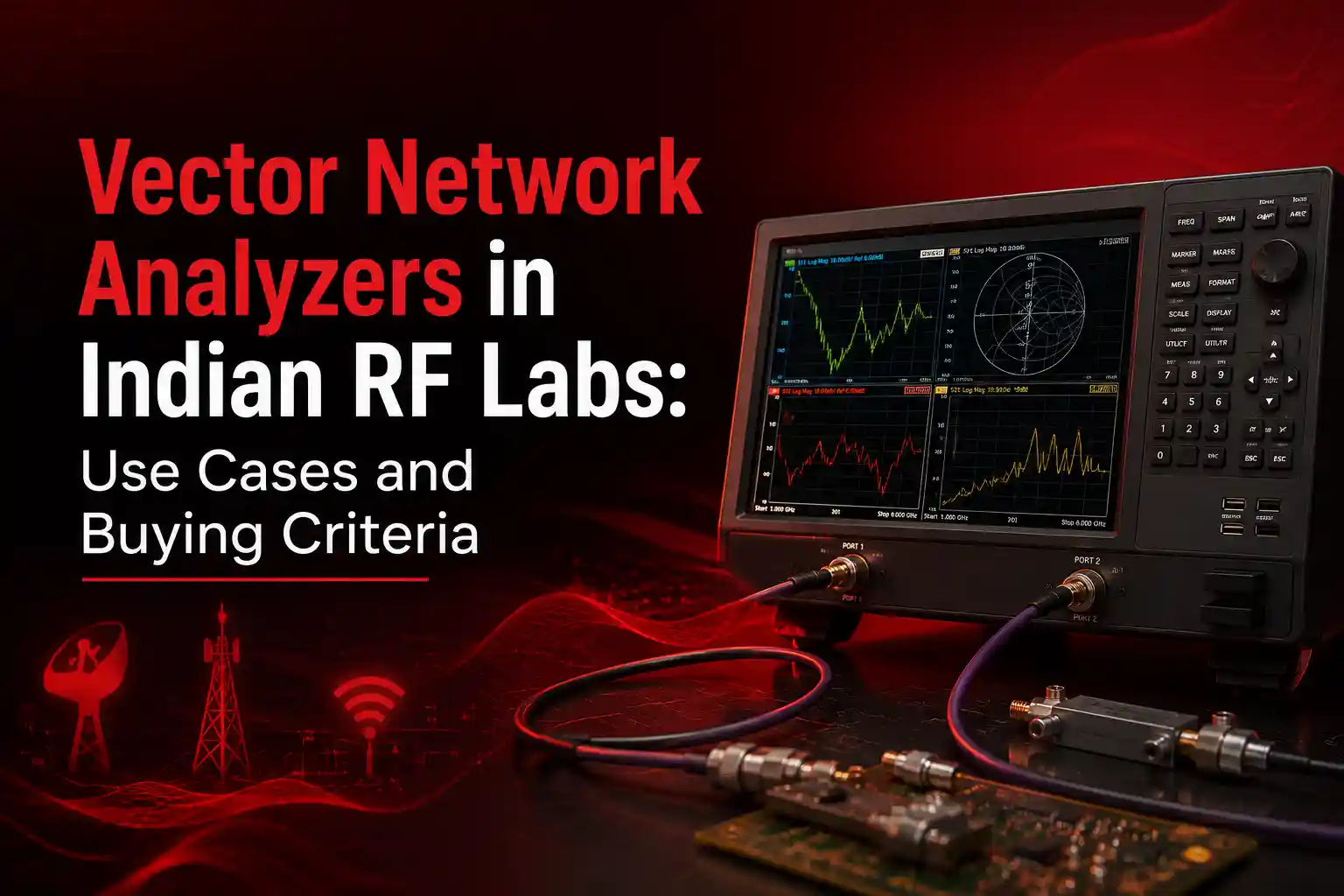
A vector network analyzer in India is a critical instrument for RF, microwave and high-frequency engineering. It measures how electrical signals behave when they pass through antennas, filters, cables, amplifiers and other components.
Indian laboratories use VNAs for product development, component validation, manufacturing tests and academic research. They are especially relevant for defence electronics, radar, satellite communications, telecommunications and semiconductor development.
However, VNA selection requires more than checking the maximum frequency. Engineers must consider dynamic range, port count, calibration methods, automation support and measurement uncertainty.
This guide explains practical VNA applications and buying criteria for Indian RF laboratories.
What Does a Vector Network Analyzer Measure?
A vector network analyzer measures how RF energy reflects from and passes through a device. It records both magnitude and phase across frequency. Engineers express these measurements as S-parameters. The results reveal impedance matching, transmission loss, gain, phase shift, isolation and signal delay.
A conventional spectrum analyzer measures signal power at different frequencies. A VNA measures the electrical response of a network.
The word “vector” refers to magnitude and phase measurement. Phase information allows engineers to examine complex impedance and transmission behaviour.
The four common two-port S-parameters are:
- S11: Input reflection coefficient
- S21: Forward transmission coefficient
- S12: Reverse transmission coefficient
- S22: Output reflection coefficient
S11 commonly indicates antenna matching or input return loss. S21 commonly represents insertion loss or forward gain.
A VNA can also calculate voltage standing wave ratio, impedance, group delay and phase response. Many systems support time-domain transformations for locating discontinuities in cables and interconnects.
Major VNA Use Cases in Indian RF Laboratories
Indian RF laboratories use VNAs to test antennas, filters, amplifiers, cables, connectors and microwave subsystems. The instrument verifies impedance, insertion loss, isolation and phase response. These measurements support design validation, production testing, failure analysis and research across telecom, aerospace, defence, automotive, semiconductor and academic applications.
Antenna Design and Validation
Antenna engineers use S11 measurements to determine impedance matching across the required frequency band.
Poor matching causes more energy to reflect towards the transmitter. This reflection can reduce radiated power and affect system performance.
Engineers can use a Smith chart to inspect complex impedance. They can then adjust matching networks, feed structures or antenna geometry.
VNAs support the development of:
- Cellular and 5G antennas
- Wi-Fi and Bluetooth antennas
- GNSS antennas
- Radar antennas
- Satellite communication antennas
- RFID antennas
- Embedded IoT antennas
The required measurement range should extend beyond the antenna’s operating band. This approach helps identify unwanted resonances.
RF Filter Testing
RF filters must pass selected frequencies and reject unwanted frequencies.
A VNA measures insertion loss, return loss, rejection, bandwidth and group delay. These results indicate whether the filter meets its design specifications.
Filter testing is important for communication receivers, radar front ends, satellite systems and spectrum management equipment.
High dynamic range becomes important when measuring deep filter rejection. Insufficient dynamic range can hide the true stop-band performance.
Amplifier and RF Front-End Testing
A VNA can measure the small-signal gain and matching characteristics of an amplifier.
S21 shows forward gain, while S11 and S22 reveal input and output matching. S12 indicates reverse isolation.
Advanced systems may support gain compression, intermodulation and nonlinear measurement options. The required feature set depends on the amplifier test plan.
Engineers must protect VNA receivers when testing active devices. External attenuators, bias networks and power control may be required.
Cable, Connector and Interconnect Testing
Cables and connectors can introduce loss, mismatch and phase variation.
VNAs help engineers identify damaged cables, poor terminations and impedance discontinuities. Time-domain functions can estimate the physical location of a fault.
High-speed digital interconnects can also be characterised using S-parameters. Frequency coverage affects defect localisation and correlation between simulation and measurement.
Defence, Radar and Aerospace Development
Radar and electronic warfare systems depend on precise RF and microwave components.
VNAs can characterise couplers, filters, antennas, phase shifters, power dividers and transmission lines. Phase accuracy becomes important in phased-array and beamforming systems.
Anritsu identifies commercial and defence systems among the applications for advanced RF and microwave S-parameter measurements.
Indian defence laboratories should also evaluate access control, data security and software deployment policies. These requirements may affect instrument configuration.
Academic and R&D Laboratories
Universities and engineering institutes use VNAs for RF teaching and research.
Students can study transmission lines, impedance matching, resonators and microwave networks. Research teams may use VNAs for material measurement, antenna development and high-speed interconnect analysis.
A laboratory should select instruments that match both current research and future project requirements.
Why S-Parameter Accuracy Matters
Accurate S-parameter measurement requires suitable frequency coverage, low trace noise, adequate dynamic range and correct calibration. Test cables, fixtures and connectors also affect results. A high-performance VNA cannot compensate for poor measurement practices. Engineers must control the complete path between the instrument and the device under test.
Measurement quality depends on the entire test setup.
A result can change because of cable movement, connector wear, temperature variation or calibration drift. These factors become more significant at higher frequencies.
Frequency Range
The VNA must cover every required operating band.
The upper frequency should provide enough margin for harmonic, broadband or future measurements. However, unnecessary frequency coverage can increase acquisition cost.
A laboratory testing sub-6 GHz devices may not require a millimetre-wave platform. A radar laboratory may need coverage extending into microwave or millimetre-wave bands.
Dynamic Range
Dynamic range determines the smallest transmission signal that the VNA can measure reliably.
It is important for:
- High-rejection filters
- High-isolation components
- Long or lossy cables
- Duplexers
- Couplers
- Antenna isolation tests
A filter with deep rejection may exceed the usable dynamic range of an entry-level instrument.
Trace Noise and Stability
Trace noise affects the repeatability of low-level measurements.
Narrower intermediate-frequency bandwidths can reduce noise. However, they also increase sweep time.
Stable test cables and connectors improve repeatability. Phase-stable cables are particularly valuable for precision measurements.
Phase and Group Delay
Magnitude alone does not describe a network completely.
Phase measurements support matching analysis, modulation studies and phased-array development. Group delay shows how transmission time changes across frequency.
Uneven group delay can distort wideband signals, even when insertion loss appears acceptable.
Vector Network Analyzer India Buying Criteria
A laboratory buying a VNA should define frequency range, dynamic range, port count, source power and measurement functions before requesting quotations. It should also examine calibration accessories, automation interfaces, software licensing, local support, warranty coverage and upgrade options. Purchase decisions should follow the laboratory’s actual device test plan.
1. Define the Device Test Plan
Begin with the devices that the laboratory must test.
List their:
- Minimum and maximum frequencies
- Expected insertion loss
- Required rejection
- Number of RF ports
- Connector types
- Power-handling limits
- Required measurement speed
- Automation requirements
This list prevents overbuying and underbuying.
2. Select the Correct Port Count
A two-port VNA is sufficient for many filters, cables and amplifiers.
A four-port instrument can measure multiport and differential devices more efficiently. It is useful for balanced components, high-speed interconnects and multiple antenna systems.
Mixed-mode parameters can be calculated from four-port single-ended measurements. The network must remain linear and time invariant for valid superposition-based results.
3. Check Source Power and Receiver Protection
Source power affects the available signal level at the device.
Lossy fixtures may require more output power. Sensitive devices may require lower and more precise power control.
Active-device measurements need proper receiver protection. The purchasing team should discuss expected device output levels with the supplier.
4. Review Calibration Options
VNA calibration removes systematic errors from the measurement path.
Common calibration approaches include:
- Short-open-load-through calibration
- Electronic calibration
- Through-reflect-line calibration
- Unknown-through calibration
- Port extension
- Fixture de-embedding
SOLT calibration uses known open, short, load and through standards to identify error terms. Vector error correction then improves measurement accuracy.
Calibration kit quality must match the connector type and frequency range.
5. Evaluate Automation Support
Production and research laboratories often need remote control.
Check support for:
- SCPI commands
- LAN, USB or GPIB control
- Python integration
- MATLAB integration
- LabVIEW integration
- Automated data export
- Limit testing
- Report generation
- Multi-instrument synchronisation
Automation support can reduce operator variation and improve throughput.
6. Examine Software Licensing
Some functions may require separate software options.
Examples include:
- Time-domain analysis
- Noise figure measurement
- Nonlinear analysis
- Material measurement
- Differential analysis
- Fixture removal
- Pulse measurements
- Spectrum analysis
The quotation should identify permanent licences, subscriptions and optional upgrades.
VNA Calibration and Measurement Workflow
A reliable VNA workflow includes instrument warm-up, connector inspection, calibration, verification and controlled device connection. Engineers should avoid moving cables after calibration. They should save calibration states and record test conditions. Verification with a known reference device confirms that the measurement system remains within the required limits.
Start by cleaning and inspecting every connector.
Damaged or contaminated connectors can create repeatability problems. They can also damage expensive calibration standards.
Allow the instrument to reach its recommended operating temperature. Connect the required cables and adapters before calibration.
Perform calibration at the device reference plane. This position should be as close as practical to the device under test.
After calibration, verify the setup with a known component. Suitable verification devices include precision airlines, attenuators or characterised filters.
Avoid excessive cable movement after calibration. Recalibrate when the setup, cable routing or temperature changes significantly.
For fixture-based testing, use de-embedding or fixture removal. Network extraction determines the S-parameters that must be removed from the measured result.
Selecting an Anritsu VNA for Indian Laboratories
Anritsu provides VNA platforms for engineering, manufacturing, education and advanced microwave research. Selection should depend on frequency coverage, dynamic range, ports, measurement speed and software requirements. Indian buyers should also consider local application support, calibration services, accessory availability and long-term expansion before choosing a specific Anritsu VNA configuration.
Anritsu offers multiple VNA product families for different performance levels.
Cost-sensitive engineering and manufacturing laboratories can examine ShockLine platforms. Anritsu describes these VNAs as economical systems for device testing, engineering and education.
Advanced research teams may require higher performance, wider frequency coverage or specialised measurements.
Explore available Anritsu Vector Network Analyzers based on your device test plan.
Laboratories building broader RF facilities can also review Anritsu RF and microwave measuring instruments.
The supplier should help confirm:
- Instrument configuration
- Compatible calibration kits
- Test cables and adapters
- Software options
- Automation requirements
- Installation and training
- Calibration support
- Warranty and service coverage
Conclusion
A vector network analyzer is central to modern RF component testing.
Indian laboratories should select VNAs through a documented test plan. Frequency range alone is not enough.
The final decision should consider measurement uncertainty, calibration, fixtures, automation and application support. A correctly configured VNA can support development, validation and production for many years.
Frequently Asked Questions About VNA India Selection
Indian buyers commonly ask about frequency range, calibration, port count and local support. The best VNA is not always the highest-frequency model. It is the instrument that measures the required devices with acceptable uncertainty, repeatability and throughput. Accessories and application support must be included in the final evaluation.
What is the difference between a VNA and a spectrum analyzer?
A VNA measures the response of a device to a controlled stimulus. It records magnitude and phase. A spectrum analyzer measures the power of signals already present at its input. It normally does not measure S-parameters.
Is a two-port VNA enough for antenna testing?
A two-port VNA is enough for basic single-antenna return-loss testing. A four-port system becomes useful for antenna isolation, MIMO systems and balanced devices.
How often should a VNA be calibrated?
The instrument itself follows the manufacturer’s calibration schedule. Measurement calibration must be performed whenever cables, fixtures, adapters or test conditions change significantly.
Does a higher maximum frequency always mean a better VNA?
No. Dynamic range, receiver noise, phase stability and calibration quality also matter. Unused frequency coverage can increase cost without improving required measurements.