
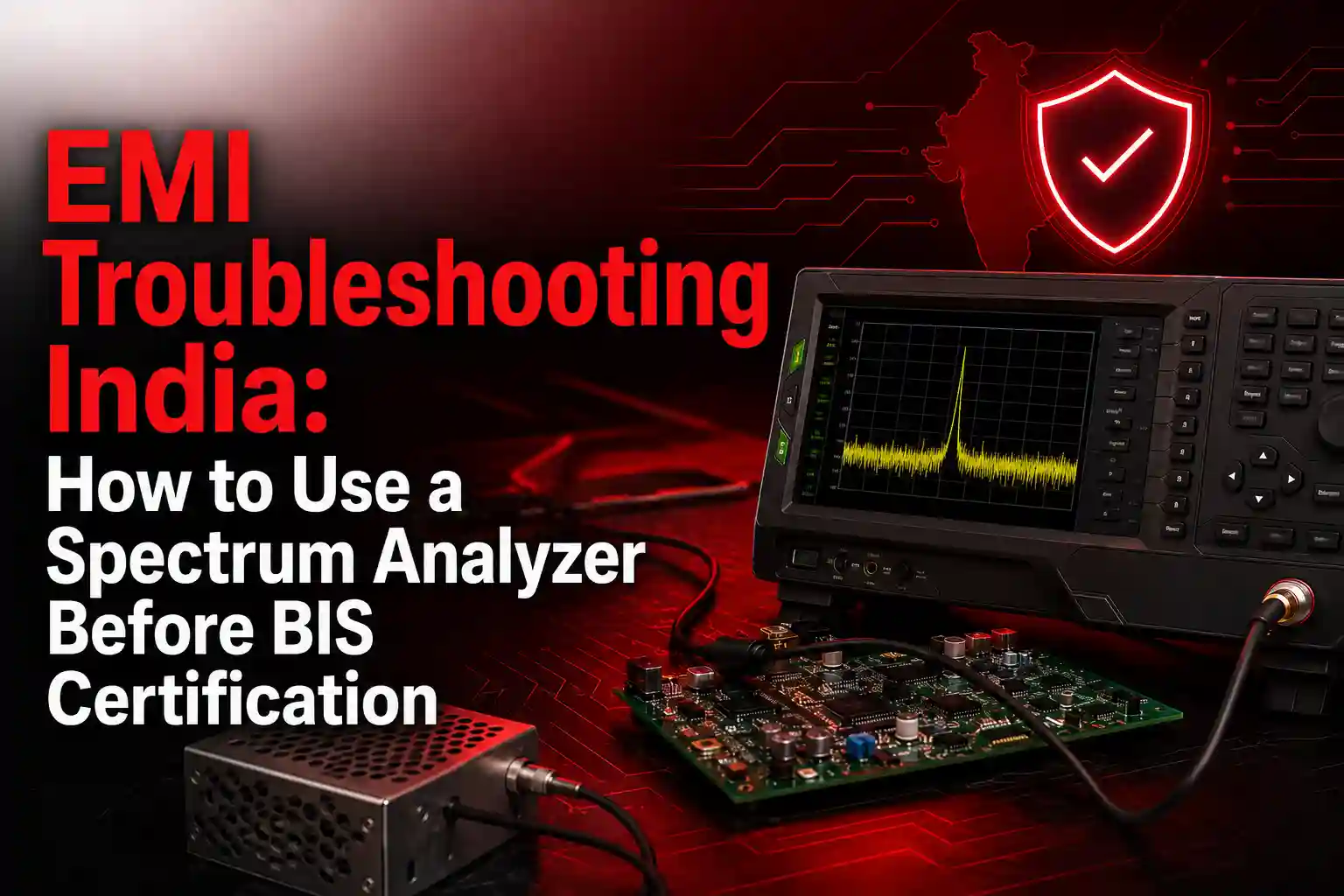
Electromagnetic interference can turn an otherwise functional electronic product into a costly compliance problem. A design may work correctly on the engineering bench but produce excessive emissions when it is connected to a power supply, communication cable, display, motor, charger, or external peripheral.
For manufacturers working on EMI troubleshooting in India, a spectrum analyzer provides a practical way to detect unwanted emissions before the product reaches a formal testing laboratory. It shows the amplitude of signals across frequency, helping engineers identify noisy clock harmonics, switching regulator emissions, cable radiation, shielding leakage, and intermittent interference.
However, pre-compliance testing must begin with the correct regulatory scope. BIS certification is generally voluntary, but it becomes mandatory for products covered by notified Quality Control Orders or the Compulsory Registration Scheme. The applicable Indian Standard determines the actual tests required.
Does BIS Certification Always Include EMI Testing?
No. EMI or EMC testing is not automatically part of every BIS certification application.
Many electronics and IT products listed under the BIS Compulsory Registration Scheme are currently evaluated against product safety standards, including IS/IEC 62368 Part 1 for audio, video, information, and communication technology equipment. Other products may have standards covering safety, performance, electromagnetic compatibility, or a combination of requirements.
EMI and EMC obligations may also arise through:
- The specific Indian Standard applicable to the product
- Telecom, wireless, automotive, medical, industrial, or lighting regulations
- Government or private procurement specifications
- Customer qualification requirements
- Export-market regulations
- Product-specific Quality Control Orders
Before building a test plan, confirm the latest product category, Indian Standard, test report format, and laboratory scope. The BIS product list continues to be amended, so an older compliance checklist may no longer be accurate.
Is BIS compliance mandatory for Indian electronics exports?
The statement “BIS compliance is mandatory for Indian electronics exports” is too broad.
BIS certification is mandatory when a notified product falls within the scope of an applicable Indian regulation or is being placed on the Indian market. Export-only products may be treated differently, and some Quality Control Orders expressly exclude goods manufactured for export. The exact wording of the relevant order must be checked rather than assuming that every exported electronic product requires BIS certification.
For exported products, manufacturers must also evaluate the rules of the destination country.
Why Pre-Compliance EMI Testing Matters
Formal EMI compliance testing uses controlled sites, calibrated equipment, specified detectors, defined measurement distances, correction factors, and documented procedures. A spectrum analyzer setup in an R&D lab cannot automatically reproduce every condition of an accredited laboratory.
Its purpose is different. Pre-compliance testing helps you:
- Identify major emissions problems before formal testing
- Compare one design revision with another
- Locate noise at PCB, enclosure, connector, or cable level
- Evaluate filters, shielding, grounding, and layout changes
- Reduce the probability of late-stage redesign
- Build measurement history for future products
Pre-compliance is effectively a simplified version of a formal emissions test. It is flexible and useful for development, but it does not replace testing by a laboratory with the required scope and facilities.
Equipment Required for Pre-Compliance EMI Testing in India
A basic setup should include the following equipment.
1. Spectrum analyzer
Select an analyzer with sufficient frequency coverage, suitable sensitivity, adjustable resolution bandwidth, peak detection, max-hold capability, and preferably EMI-specific detectors and limit-line functions.
Modern instruments may also provide quasi-peak and average detectors, EMI resolution bandwidths, real-time spectrum analysis, spectrograms, correction tables, and automated reporting. These features make it easier to move from a broad scan to detailed troubleshooting.
You can review suitable Spectrum Analyzers for benchtop, portable, real-time, and general RF measurement applications.
2. Near-field probes
Near-field probes help locate emissions directly on the PCB or around connectors, cables, enclosure openings, and power components.
- H-field probes respond primarily to magnetic fields created by current loops.
- E-field probes are useful around high-voltage or high-impedance nodes and areas with strong capacitive coupling.
Probe kits often contain different loop sizes. A larger probe offers better sensitivity for initial scanning, while a smaller probe provides improved spatial resolution when narrowing down the source. Anritsu near-field probe sets, for example, include both magnetic and electric probes for resolving emissions over a broad frequency range.
3. LISN for conducted emissions
A Line Impedance Stabilization Network provides a controlled impedance and couples conducted RF noise from the product’s power input to the measuring instrument.
Never connect a spectrum analyzer directly to AC mains. Use a correctly rated LISN, suitable transient protection or limiter, and the grounding arrangement specified by the equipment manufacturer.
4. Antennas and accessories
For preliminary radiated testing, you may also need:
- Broadband EMI antenna
- Low-noise preamplifier
- RF attenuator or transient limiter
- Low-loss coaxial cables
- Tripod or antenna stand
- Ground plane
- Current probe for cable measurements
- Non-conductive DUT support
EMI Troubleshooting India: Step-by-Step Spectrum Analyzer Workflow
Step 1: Identify the applicable standard and operating conditions
Do not begin by choosing arbitrary analyzer settings.
First identify:
- The product category
- Applicable Indian Standard
- Required conducted and radiated test bands
- Product classification
- Detector requirements
- Measurement bandwidths
- Required product operating modes
- Cable and peripheral configuration
Test the device in the operating condition most likely to create emissions. This may include maximum processor activity, full communication traffic, highest display resolution, motor operation, battery charging, maximum converter load, or continuous wireless transmission.
Step 2: Record the ambient spectrum
Before powering the device under test, scan the test environment and save the result.
This ambient scan reveals FM radio, television, mobile, Wi-Fi, industrial equipment, LED lighting, and other external signals. Without this reference, an engineer may spend hours attempting to fix an emission that is not coming from the product.
Next, power the DUT and compare the two traces. Signals that appear or increase significantly are likely to be associated with the product. Ambient scans are a standard part of practical pre-compliance diagnosis.
Step 3: Configure the spectrum analyzer
Use the applicable standard for the final settings. As an initial CISPR-oriented reference, conducted emissions are commonly investigated from 150 kHz to 30 MHz, while preliminary radiated emissions scans often begin at 30 MHz and continue to 1 GHz or higher, depending on the product and standard.
A practical starting configuration is:
- Detector: Peak
- Trace: Max hold
- Scale: Logarithmic amplitude
- Input attenuation: High enough to avoid overload
- Preamplifier: Off initially
- Resolution bandwidth: Set according to the applicable standard
- Sweep time: Long enough for stable detection
- Limit lines: Load when available
Common CISPR measurement bandwidths include 9 kHz for parts of the conducted emissions range and 120 kHz for radiated measurements between 30 MHz and 1 GHz. These are EMI bandwidths and may differ from ordinary spectrum analyzer filter definitions. Always use the exact settings specified by the applicable standard.
Use peak detection for a fast prescan. Investigate frequencies close to or above the limit using quasi-peak and average detectors where required. Peak detection is efficient because it provides a conservative initial view, while quasi-peak measurements account for the repetition characteristics of the disturbance.
Step 4: Check for analyzer overload
A strong out-of-band signal can overload the analyzer input and create false responses.
Increase the input attenuation and observe the display. If several signal levels change unexpectedly, the analyzer may have been overloaded. Use additional attenuation, filtering, or a preselector before trusting the result.
Enable the preamplifier only when measuring weak signals and after confirming that strong signals will not overload the front end.
Step 5: Scan the PCB with near-field probes
Begin with a larger H-field loop and scan the entire PCB. Maintain a consistent probe height and orientation so that measurements remain comparable.
Pay particular attention to:
- Switching regulators
- Inductors and transformers
- Crystal oscillators
- High-speed processors and memory
- Clock distribution paths
- Display interfaces
- DC power connectors
- Communication ports
- PCB edges and return-path discontinuities
Once a noisy region is found, change to a smaller probe. Rotate the probe while watching the signal level because magnetic coupling depends strongly on orientation.
Near-field testing is particularly valuable because a far-field antenna can show that a product has an emissions problem but may not identify the component, trace, opening, or cable responsible.
Step 6: Match emissions with circuit frequencies
Look for relationships between measured peaks and known operating frequencies.
For example, a 25 MHz clock may produce emissions at 50 MHz, 75 MHz, 100 MHz, and higher harmonics. A switching converter may create a lower-frequency fundamental accompanied by a broad set of harmonics caused by fast switching edges and ringing.
Change one operating condition at a time:
- Reduce processor activity
- Disable a communication interface
- Change converter load
- Disconnect a display cable
- Stop a motor
- Switch between battery and adapter power
- Change firmware modes
When an emission changes with a specific function, you have established a useful correlation.
For short bursts, frequency-hopping noise, or emissions that appear only during startup, a real-time spectrum analyzer or spectrogram can be more effective than a traditional swept analyzer. Real-time instruments are designed to capture transient events that may occur between conventional sweeps.
Step 7: Measure conducted emissions
Connect the product through the LISN and connect the LISN measurement output to the analyzer through the appropriate protection device.
Run a peak prescan, then examine frequencies close to the limit with the required detectors. Apply the LISN, cable, attenuator, and limiter correction factors where necessary.
If emissions are high, investigate:
- Input filter placement
- Common-mode and differential-mode noise
- Converter switching loops
- Chassis and signal grounding
- Y-capacitor configuration
- Cable shield termination
- Return paths around connectors
Step 8: Perform a preliminary radiated scan
Use a broadband antenna in the quietest practical location available. Maintain a fixed antenna distance and record the setup so that future measurements are repeatable.
Rotate the DUT, change antenna polarization, and reposition external cables. A large change caused by cable movement usually indicates common-mode current on that cable.
An office or ordinary workshop will contain reflections and ambient transmitters, so treat the results as comparative engineering data rather than certification-grade measurements.
Turning Spectrum Peaks into Design Fixes
A useful troubleshooting model is source, coupling path, and radiator.
| Observed behaviour | Possible cause | Corrective direction |
| Narrow peaks at clock harmonics | Clock or digital return-path problem | Reduce loop area, improve return continuity, add source damping |
| Broad noise around a converter frequency | Switching edges or ringing | Improve power layout, evaluate snubbers, filtering, and gate resistance |
| Peak changes when a cable is moved | Cable common-mode current | Improve connector filtering, shield bonding, or common-mode choking |
| Emission leaks near an enclosure seam | Inadequate shielding continuity | Improve seam contact, gasket design, grounding, or aperture control |
| Short intermittent bursts | Firmware state, radio activity, or load transition | Use real-time capture, triggering, and operating-state correlation |
Make one modification at a time and repeat the same measurement. Multiple simultaneous changes may reduce emissions, but they make it difficult to determine which correction was effective.
Maintain a Practical Compliance Margin
Do not design a product that only touches the limit line in your internal setup. Differences in antennas, cables, site reflections, ambient noise, product samples, temperature, and laboratory uncertainty can change the final result.
A 6 dB internal warning margin is a useful screening threshold. Greater margin, such as 10 dB, may be preferable when the pre-compliance environment has significant uncertainty.
Choosing a Spectrum Analyzer for EMI and EMC Testing
For pre-compliance EMI in India, evaluate more than the maximum frequency printed on the instrument.
Important specifications include:
- Frequency range
- Displayed average noise level
- Dynamic range
- EMI resolution bandwidths
- Peak, quasi-peak, and average detectors
- Sweep speed
- Real-time analysis bandwidth
- Spectrogram and persistence displays
- Limit-line and correction-factor support
- Portability
- Reporting and automation functions
For intermittent noise, field measurements, and advanced RF analysis, review the available Anritsu Signal and Spectrum Analyzers. Relevant models and configurations can support EMI detectors, pre-compliance measurements, high-sensitivity analysis, and transient interference investigation.
Common EMI Troubleshooting Mistakes
Avoid these frequent errors:
- Testing without confirming the applicable standard
- Ignoring ambient signals
- Using the preamplifier before checking for overload
- Changing probe distance and orientation between measurements
- Comparing raw traces without cable, antenna, or LISN correction factors
- Testing only one operating mode
- Treating an office scan as a formal compliance result
- Making several design changes before re-measuring
- Stopping once the trace falls barely below the limit
Conclusion
A spectrum analyzer gives electronics teams a practical way to find EMI problems before they become laboratory failures. The most effective process is to confirm the applicable standard, capture an ambient baseline, perform a peak prescan, localize emissions with near-field probes, investigate conducted and radiated paths, and repeat the same measurement after every design change.
Pre-compliance testing does not replace formal EMI EMC testing in India, but it gives engineers better evidence, faster design feedback, and more confidence before submitting a product for BIS or other regulatory evaluations.
Build a More Reliable EMI Pre-Compliance Setup
Explore RevineTech’s range of Spectrum Analyzers or compare Anritsu Signal and Spectrum Analyzers for EMI troubleshooting, transient interference capture, RF analysis, and pre-compliance measurements.
Choose your analyzer based on the applicable frequency range, EMI detector requirements, sensitivity, real-time capabilities, and laboratory workflow rather than frequency coverage alone.
Frequently Asked Questions
Can a spectrum analyzer replace an EMI receiver?
A spectrum analyzer can be highly effective for EMI debugging and pre-compliance testing when it supports suitable bandwidths, detectors, correction factors, and sensitivity. It does not automatically replace the compliant receiver, calibrated transducers, controlled site, and prescribed procedures required for formal testing.
Does every BIS-certified electronic product require EMI/EMC testing?
No. The required tests depend on the notified product category and applicable Indian Standard. Some BIS standards primarily address electrical or product safety, while others may contain performance or EMC requirements. Separate regulations may also apply to telecom, wireless, automotive, medical, lighting, and industrial equipment.
Should I use an H-field or E-field probe first?
An H-field probe is generally a practical starting point for PCB scanning because many emissions originate from high-frequency current loops. Use an E-field probe when investigating high-voltage nodes, capacitive coupling, enclosure openings, connectors, or electric-field leakage.
Why use peak detection before quasi-peak?
Peak detection scans quickly and highlights the worst instantaneous levels. It is therefore useful for locating suspect frequencies. Quasi-peak and average measurements are slower and should be applied to the important frequencies identified during the prescan.
Can EMI testing be performed inside a normal office?
An office setup can provide useful comparative measurements, especially for PCB probing and checking whether a modification reduces an emission. It cannot reliably reproduce a certified chamber or open-area test site because of ambient transmissions, reflections, grounding differences, and uncontrolled measurement geometry.