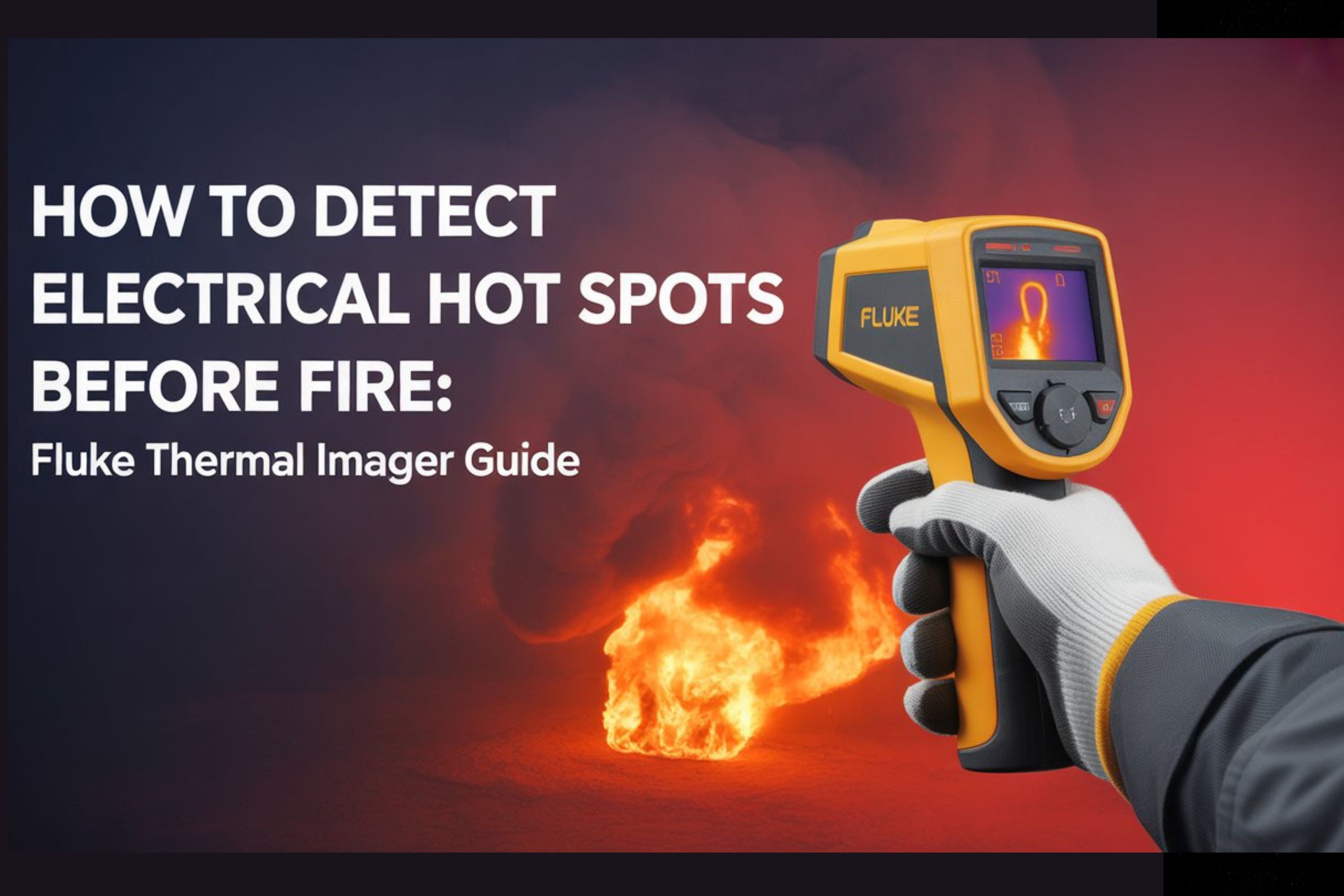
How to Detect Electrical Hot Spots Before They Cause Fire: Complete Guide with Fluke Thermal Imagers
Electrical fires remain one of the most devastating and preventable hazards in industrial facilities, commercial buildings, and manufacturing plants. Every year, thousands of electrical failures result in fires that cause extensive property damage, production downtime, and in tragic cases, loss of life. The alarming reality is that most of these fires could have been prevented if the warning signs had been detected early enough.
This is where thermal imaging technology transforms electrical maintenance from reactive firefighting into proactive prevention. When you understand how to properly use Fluke thermal imagers for electrical inspections, you gain the ability to literally see heat building up in electrical components long before they reach dangerous failure points. Think of it as giving yourself X-ray vision for heat, allowing you to spot problems that remain completely invisible to the naked eye until it's too late.
In this comprehensive guide, we'll walk you through everything you need to know about detecting electrical hot spots before they escalate into fire hazards. Whether you're an electrical contractor, facility maintenance technician, or safety manager, you'll learn the fundamental principles of thermal inspection, specific techniques for scanning different electrical equipment, and critical temperature thresholds that separate normal operation from dangerous conditions.
Understanding Why Electrical Components Create Hot Spots
Before we dive into detection techniques, it's important to understand the physics behind why electrical equipment generates excessive heat in the first place. When electrical current flows through a conductor, it naturally produces some heat due to electrical resistance. This is completely normal and expected. However, when certain failure conditions develop, the resistance increases dramatically, and the heat generation accelerates to dangerous levels.
The most common cause of electrical hot spots is poor connections. When terminal connections loosen over time due to thermal cycling, vibration, or improper installation torque, the contact resistance at that junction increases significantly. As current continues to flow through this high-resistance connection, it generates far more heat than the same current would produce in a properly tightened connection. This creates a dangerous feedback loop where heat causes further expansion and loosening, which increases resistance even more, generating additional heat.
Corrosion presents another major pathway to hot spot development. When moisture, chemical contaminants, or simple oxidation affects connection surfaces, it creates a resistive layer between conductors. This invisible barrier forces current to flow through a smaller effective contact area, concentrating the current density and dramatically increasing heat generation at that specific point.
Overloading occurs when electrical components carry more current than they were designed to handle safely. Each conductor, circuit breaker, and connection has a rated capacity based on its ability to dissipate heat while maintaining safe operating temperatures. When you exceed these ratings, even perfectly installed and maintained equipment will generate excessive heat that can lead to insulation failure, component degradation, and ultimately fire.
Imbalanced loads in three-phase systems create another subtle but dangerous condition. When the current distribution across the three phases becomes significantly unequal, it causes excessive current flow through neutral conductors and creates unusual heating patterns in transformers, motors, and distribution equipment. A Fluke infrared camera can reveal these imbalances through characteristic temperature patterns that would be nearly impossible to detect through conventional testing methods.
The Science Behind Thermal Imaging for Electrical Inspections
Understanding how professional thermography cameras work will help you use them more effectively and interpret the images correctly. Every object above absolute zero temperature emits infrared radiation as part of the electromagnetic spectrum. The hotter an object becomes, the more infrared energy it radiates. While our eyes cannot see this infrared radiation, thermal imaging cameras contain special sensors that detect these wavelengths and convert them into visible images where different temperatures appear as different colors.
When you point a thermal camera for electrical inspections at an electrical panel or piece of equipment, it's measuring the infrared radiation emitted from every surface in its field of view. Modern industrial thermal imaging tools can detect temperature differences as small as a fraction of a degree, allowing you to spot subtle temperature variations that indicate developing problems. The camera processes millions of temperature measurements and displays them as a thermal image where hot areas typically appear as bright colors like red, orange, and yellow, while cooler areas show as darker colors like blue and purple.
However, there's an important concept you need to understand called emissivity. Different materials emit infrared radiation with different efficiency even when they're at the same temperature. Dull, oxidized, or painted surfaces have high emissivity and radiate infrared energy very efficiently, making them easy to measure accurately. Shiny, reflective metal surfaces have low emissivity and reflect infrared radiation from other sources rather than emitting their own. This means that when you're scanning polished copper bus bars or shiny aluminum conductors, you need to be aware that the temperature reading might not be entirely accurate without proper compensation.
Fluke thermal imagers include emissivity adjustment settings that allow you to compensate for different surface materials. For most electrical inspections, you'll be looking at equipment enclosures, insulation materials, and connection points that have relatively high emissivity, so the default settings work well. The key is understanding that you're primarily looking for temperature differences and patterns rather than absolute temperature values. A connection that's twenty or thirty degrees hotter than similar connections nearby is cause for concern regardless of whether the absolute temperature reading is perfectly calibrated.
Essential Safety Protocols Before Starting Electrical Thermal Inspections
Safety must always be your first priority when conducting electrical inspections, and thermal imaging actually makes inspections significantly safer by allowing you to scan equipment from a safe distance without requiring physical contact. However, you still need to follow proper safety protocols because you'll be working around energized electrical equipment.
Personal protective equipment requirements depend on the voltage levels and arc flash hazard category of the equipment you're inspecting. At minimum, you should wear safety glasses with side shields and voltage-rated gloves when working around exposed electrical components. For higher-energy systems, you may need a full arc-rated face shield, arc-rated clothing, and hearing protection. Always consult your facility's arc flash hazard analysis and follow the personal protective equipment requirements specified in NFPA 70E standards.
The equipment being inspected must be energized and under at least forty percent of its normal operating load for thermal imaging to be effective. This is because thermal anomalies only appear when current is flowing through the components. An electrical panel with no load might look perfectly normal in a thermal image even if it has loose connections that would create dangerous hot spots under full current flow. This means you need to schedule inspections during normal operating hours when equipment is actually working rather than during shutdown periods.
Maintain proper standoff distances when scanning electrical equipment. Even though thermal cameras allow you to inspect from several feet away, you need to respect minimum approach distances for the voltage levels involved. The higher the resolution of your Fluke infrared camera, the farther away you can stand while still capturing useful detail. This is why professional-grade thermal imaging tools with higher resolution sensors are worth the investment for electrical work because they enhance both the quality of your inspections and your personal safety.
Before beginning any inspection, inform relevant personnel that you'll be conducting thermal scans and ensure that no one will be opening electrical enclosures, switching loads, or performing maintenance during your inspection. You need stable operating conditions to get meaningful thermal images and establish accurate baselines for comparison.
Systematic Scanning Techniques for Different Electrical Equipment
The key to effective electrical thermal inspections is developing a systematic approach that ensures you don't miss critical components. Random scanning might catch obvious problems, but a structured methodology will reveal subtle developing issues before they become serious.
When inspecting electrical distribution panels, start by scanning the entire panel from a distance to get an overview thermal image. This wide view often reveals patterns and anomalies that might not be apparent when you're focused on individual components. Look for any areas that appear significantly warmer than the surrounding equipment. Once you've identified potential hot spots, move closer and use your camera's zoom or higher resolution mode to examine those areas in detail.
Systematically scan each row of circuit breakers from top to bottom, looking for breakers that run hotter than others carrying similar loads. A breaker that's significantly warmer than its neighbors is often indicating an overload condition, a failing internal mechanism, or poor connection to the bus bar. Pay particular attention to the connection points where the breaker contacts the bus bar because this is where contact resistance problems often develop.
Main bus bars and distribution lugs require careful attention because they carry large currents where even small resistance increases create substantial heat. Scan along the entire length of bus bars looking for localized hot spots that indicate poor bolted connections or internal damage. The temperature should be relatively uniform along properly functioning bus bars. When you see a distinct hot spot at a specific location, it's telling you that resistance is elevated at that exact point.
Terminal blocks and wire connections deserve special scrutiny because they're among the most common failure points in electrical systems. When scanning terminal strips, look for individual terminals that are hotter than adjacent terminals carrying similar current. This temperature differential immediately tells you that the connection resistance is higher than it should be. Use your thermal camera's measurement tools to document the temperature difference between the suspect connection and reference connections nearby.
Motor control centers present unique challenges because they contain numerous contactors, overload relays, and control circuits in addition to power connections. When scanning motor starters, pay attention to the contactor terminals where power wires connect. These high-current connections can develop significant heating if they loosen over time. Also scan the overload relay heater elements, though remember that these are designed to generate heat under load, so you're looking for asymmetry between phases rather than absolute temperature.
Transformers should show relatively uniform temperature distribution across their enclosures when operating normally. Hot spots on transformer cases can indicate internal winding problems, core lamination issues, or failing cooling systems. Scan all sides of the transformer enclosure and note any areas that are significantly hotter than the general case temperature. For liquid-filled transformers, temperature differences between the top and bottom of the tank can indicate problems with internal oil circulation.
Switchgear and bus duct systems require scanning of all accessible sections looking for localized heating at joints, connections, and transition points. These systems are designed to carry large currents with minimal temperature rise, so any hot spots are significant. Many Fluke thermal imagers include measurement tools that let you compare temperatures across multiple points simultaneously, which is particularly useful when scanning long runs of bus duct to identify problematic sections.
Temperature Thresholds and Interpretation Guidelines
Understanding what temperature readings actually mean is crucial for making correct assessment decisions. Simply seeing a warm spot doesn't automatically indicate a problem because all current-carrying components generate some heat during normal operation. You need to interpret temperatures in context by comparing them to baseline values, similar components, and established industry guidelines.
The most reliable assessment method is comparing the temperature of a suspect component to the temperature of similar components operating under similar load conditions. For example, if you're scanning a three-phase connection and phases A and B are reading seventy-five degrees Celsius while phase C is reading one hundred and five degrees Celsius, that thirty-degree temperature differential clearly indicates a problem with phase C even though none of the individual readings might seem alarmingly high in isolation.
As a general guideline for electrical connections, a temperature difference of fifteen degrees Celsius or more between similar components operating under similar conditions indicates a developing problem that should be investigated further. When the temperature differential reaches thirty degrees Celsius or higher, you're looking at a condition that requires immediate attention because the elevated resistance is generating substantial excess heat that will accelerate component degradation.
Industry standards like NFPA 70B provide more specific guidance based on research into electrical system failures. These standards typically classify thermal anomalies into priority levels based on severity. A component operating ten to thirty degrees above similar components under similar load might be classified as a priority three condition requiring repair at the next scheduled maintenance. A component running thirty to fifty degrees hotter than references becomes a priority two requiring repair within a few weeks. Components showing temperature differences exceeding fifty degrees or any component approaching its rated temperature limits becomes a priority one emergency requiring immediate corrective action.
It's important to understand that these temperature differentials are more significant than absolute temperature values because they account for ambient conditions, load levels, and normal operating temperatures. A circuit breaker that reads ninety degrees Celsius might be perfectly normal if the surrounding breakers under similar load are also reading ninety degrees. But that same breaker reading ninety degrees when similar breakers are reading sixty degrees is telling you that something is wrong with that specific breaker.
When documenting thermal anomalies, always record both the absolute temperature of the hot spot and the reference temperature of similar nearby components. This gives you the temperature differential which is the most important diagnostic indicator. Modern professional thermography cameras from Fluke include annotation tools that let you mark reference points and automatically calculate temperature differences, which significantly improves the accuracy and usefulness of your inspection reports.

Common Electrical Hot Spot Scenarios and Their Thermal Signatures
Recognizing characteristic thermal patterns helps you quickly identify specific types of electrical problems. Each failure mode produces a distinctive temperature signature that you'll learn to recognize with experience.
Loose electrical connections typically produce sharply defined hot spots exactly at the point where the connection resistance is elevated. You'll see a bright spot on the terminal or lug that's significantly hotter than the conductor leading up to it. The temperature often drops off quickly as you move away from the actual connection point because the metal conductor efficiently dissipates heat. This concentrated, localized heating pattern is the hallmark of a high-resistance connection.
Overloaded circuits produce a different thermal signature characterized by uniformly elevated temperatures across multiple components in the circuit path. When a circuit breaker, conductors, and connection points all show elevated temperatures compared to similar nearby circuits, it indicates that the current flowing through that entire circuit is excessive. Unlike loose connections which create localized hot spots, overload conditions create broadly distributed heating.
Corroded connections often show moderate temperature elevation with less dramatic hot spots than purely mechanical loose connections. This is because corrosion typically increases resistance more gradually and across a larger contact area. You might see a terminal that's fifteen to twenty-five degrees warmer than similar connections without the sharp, intense hot spot characteristic of a severely loose connection. These moderate but persistent temperature elevations are easy to overlook but represent real problems that will worsen over time.
Imbalanced three-phase systems produce distinctive patterns where one phase consistently runs hotter than the other two phases across multiple measurement points. When you scan a three-phase panel or motor connection and see that phase B terminals, conductors, and circuit breakers are all warmer than phases A and C, it indicates that phase B is carrying more current than the other phases. This imbalance can result from unequal load distribution or from problems in the upstream distribution system.
Failing circuit breakers sometimes show heating in the breaker mechanism itself rather than at connection points. When the internal contacts or trip mechanism begin to degrade, the breaker may run warmer than adjacent breakers even when carrying similar or lighter loads. This internal heating pattern, where the entire breaker body is elevated in temperature rather than just the terminal connections, suggests problems with the breaker's internal components.
Arcing faults create intermittent but extremely intense hot spots that may appear and disappear as the arc strikes and extinguishes. These are among the most dangerous conditions because arcing represents partial electrical breakdown that can rapidly escalate to full short circuits and fires. If you observe flickering or intermittent hot spots during your inspection, treat it as an emergency condition requiring immediate attention.
Integrating Thermal Imaging into Your Preventive Maintenance Program
The real power of industrial thermal imaging tools emerges when you integrate thermal scanning into your regular preventive maintenance schedule rather than treating it as an occasional troubleshooting tool. Establishing a routine thermal inspection program allows you to detect problems in their earliest stages and track the progression of developing issues over time.
Begin by creating a baseline thermal survey of all critical electrical equipment when it's in good operating condition. These baseline images provide reference points for future inspections, allowing you to identify changes from normal operating patterns. Store these baseline images in your computerized maintenance management system along with the operating conditions at the time they were captured, including load levels, ambient temperature, and equipment configuration.
Schedule regular thermal inspections based on the criticality and operating conditions of your electrical equipment. Critical distribution equipment that feeds essential processes might warrant monthly thermal inspections, while less critical circuits could be inspected quarterly or annually. Equipment operating in harsh environments with temperature extremes, vibration, or contamination typically needs more frequent inspection than equipment in controlled environments.
Develop standardized inspection routes and procedures to ensure consistency between inspections. When different technicians follow the same scanning pattern and document findings using the same protocols, it becomes much easier to compare results over time and identify developing trends. Your thermal inspection procedure should specify which equipment to scan, what viewing angles to use, what measurements to record, and how to document findings in a consistent format.
Trending analysis becomes possible when you've conducted multiple thermal inspections of the same equipment over time. By comparing current thermal images to previous inspections, you can identify components that are showing gradually increasing temperatures even if they haven't yet exceeded action thresholds. This trending capability allows you to schedule repairs proactively during planned maintenance windows rather than responding to emergency failures during production hours.
Link your thermal inspection findings to your work order system so that identified problems automatically generate corrective maintenance tasks with appropriate priority levels. A priority one thermal finding should immediately create an emergency work order, while lower priority findings can be scheduled for the next appropriate maintenance window. This integration ensures that thermal inspection findings translate into actual corrective action rather than just documentation that sits in a filing cabinet.
Many Fluke thermal imagers include connectivity features that allow you to transfer images to your computer or mobile device for analysis and reporting. Take advantage of these capabilities to create professional thermal inspection reports that include thermal images, temperature measurements, recommended actions, and follow-up tracking. When you can show management concrete evidence of problems detected and prevented through thermal imaging, it becomes much easier to justify the investment in quality equipment and maintain support for your preventive maintenance program.
Advanced Tips for Getting the Most from Your Fluke Infrared Camera
Once you've mastered basic thermal scanning techniques, these advanced tips will help you capture more useful thermal data and make more accurate assessments.
Understanding your camera's spatial resolution capabilities helps you maintain appropriate scanning distances. Spatial resolution, often specified as the instantaneous field of view or measurement spot size ratio, determines how far away you can be from a target while still accurately measuring its temperature. A thermal camera with better spatial resolution can detect smaller hot spots from greater distances. This matters for electrical work because many electrical components are small, and you need to maintain safe standoff distances. Check your camera's specifications and use the distance-to-spot size calculator to ensure you're close enough to accurately measure the features you're inspecting.
The fusion features available in many Fluke thermal imagers significantly improve your ability to document and communicate findings. These tools overlay thermal images onto corresponding visible light photographs, making it much easier to identify exactly which component or connection is showing the thermal anomaly. When you're creating reports for maintenance teams who will perform repairs, fusion images eliminate ambiguity about which of dozens of similar-looking terminals needs attention.
Adjust your camera's temperature scale and color palette to optimize the contrast for the conditions you're viewing. Auto-scaling modes work well for general scanning, but sometimes manually setting the temperature range helps you see subtle temperature differences more clearly. If you're scanning an electrical panel where everything is between sixty and ninety degrees Celsius, manually setting that temperature range will spread those thirty degrees across your full color palette, making it easier to distinguish ten-degree differences than if your scale was auto-ranging from twenty to two hundred degrees.
Environmental conditions affect thermal imaging more than many users realize. Reflections from hot or cold objects can create false hot spots or cold spots in your thermal images, particularly when scanning shiny surfaces. Be aware of what's around and behind the equipment you're scanning. That apparent hot spot on a polished bus bar might actually be a reflection of a hot light fixture or heating duct rather than an actual hot spot on the bus bar itself. Changing your viewing angle or using different emissivity settings can help you distinguish real hot spots from reflections.
Wind and air movement can significantly affect thermal measurements by cooling surfaces through convection. When scanning outdoor electrical equipment or gear located near HVAC vents, be aware that forced air flow can mask temperature rises or create misleading thermal patterns. If possible, conduct inspections when HVAC systems are in steady-state operation to ensure consistent conditions.
Measuring ambient temperature and recording it with your thermal images provides important context for interpreting your results. A connection reading ninety degrees Celsius is much more concerning on a cool morning when ambient temperature is twenty degrees than on a hot summer afternoon when ambient temperature is thirty-five degrees. Some Fluke infrared cameras include ambient temperature sensors that automatically record this information with your images.
Comprehensive Inspection Workflow from Planning Through Documentation
Implementing an effective thermal inspection program requires more than just owning a thermal camera. Following a structured workflow ensures you consistently capture useful data and translate findings into preventive action.
The planning phase begins with identifying which equipment will be inspected and scheduling inspections during appropriate operating conditions. Coordinate with operations staff to ensure equipment will be under representative load during your inspection window. Gather any previous thermal inspection reports to identify equipment with known developing issues that require close attention and trending analysis.
Safety preparation includes verifying personal protective equipment requirements, obtaining necessary electrical work permits if required by your facility, and notifying control room operators or facility management that thermal inspections will be occurring. Review arc flash labels on equipment you'll be inspecting to ensure you understand the hazard levels and protection requirements.
Equipment preparation means ensuring your thermal camera battery is fully charged and you have spare batteries if you'll be conducting an extended inspection. Verify that your camera's date and time settings are correct so that your image timestamps will be accurate. Clean your camera's infrared lens according to manufacturer recommendations because dust or smudges can affect image quality and temperature accuracy.
During the inspection, work systematically through your planned inspection route, capturing both wide-angle overview images and detailed close-up images of any anomalies you identify. Use your camera's annotation features to voice-record notes about operating conditions, unusual observations, or specific concerns for later reference. Take multiple images from different angles when you identify hot spots to fully document the condition and help technicians locate the problem during repairs.
Immediate assessment in the field allows you to identify emergency conditions that require immediate response. When you discover priority one conditions with severe overheating or dangerous temperature differentials, notify appropriate personnel immediately so that emergency repairs or equipment isolation can be initiated. Don't wait to complete your entire inspection before reporting critical safety issues.
Post-inspection analysis involves reviewing all captured thermal images, comparing them to baseline and previous inspection data, and classifying findings according to severity. This is when you make final determinations about which conditions require immediate action, which should be scheduled for upcoming maintenance, and which are acceptable for continued monitoring.
Documentation should include thermal images with appropriate annotation, temperature measurements including both absolute values and temperature differentials, comparison to previous inspections showing any trending, and specific recommended corrective actions with appropriate priority levels. Professional thermal inspection reports generated from modern Fluke thermal imagers provide all this information in a clear format that maintenance teams can act upon.
Follow-up tracking ensures that identified problems actually get repaired. Create work orders for each corrective action with appropriate priority levels and track them through completion. After repairs are made, conduct follow-up thermal inspections to verify that corrective actions were effective and temperatures have returned to normal levels. This closed-loop process ensures that your thermal inspection program actually prevents failures rather than simply documenting them.
Building Competency in Electrical Thermography
Becoming proficient at electrical thermal inspection requires more than just buying a thermal camera and pointing it at electrical equipment. Developing real competency involves understanding electrical systems, thermal imaging principles, and interpretation techniques that come from training and experience.
Formal thermography training through certification programs like those offered by the Infrared Training Center or ASNT provides structured learning in thermal imaging fundamentals, electrical system inspection techniques, and industry best practices. These programs teach you proper camera operation, factors affecting thermal measurements, interpretation guidelines, and report writing standards. Many organizations require thermographers to achieve Level I or Level II certification to ensure competency in thermal inspection techniques.
Understanding electrical systems and their failure modes is equally important as camera operation skills. The best thermographers combine thermal imaging knowledge with deep understanding of electrical engineering principles. Study common electrical failure mechanisms, how different types of connections are constructed, what causes contact resistance to increase, and how electrical equipment is designed to dissipate heat under normal operating conditions. This electrical knowledge allows you to look at a thermal pattern and immediately understand what it's telling you about the underlying electrical condition.
Practice regularly by conducting thermal inspections even when you're not specifically troubleshooting problems. The more thermal images you capture of normally operating equipment, the better you'll become at recognizing what normal looks like versus what indicates developing problems. This experience builds your intuition for thermal patterns and helps you distinguish real anomalies from normal temperature variations.
Study thermal images from others in your field by joining professional thermography groups, attending conferences, and reviewing published case studies. Seeing how other thermographers document and interpret thermal findings expands your perspective and exposes you to situations you might not encounter in your own facility. Online thermography communities often share interesting images and discuss interpretation challenges, providing valuable learning opportunities.
Keep current with equipment technology and industry standards because both evolve over time. Modern professional thermography cameras offer capabilities that weren't available in earlier models, and understanding how to use new features like super-resolution, thermal fusion, or advanced measurement tools can significantly improve your inspection effectiveness. Similarly, electrical codes and inspection standards are periodically updated to reflect new understanding of electrical system failures and thermal inspection best practices.
Return on Investment and Making the Business Case
Investing in quality industrial thermal imaging tools and implementing a comprehensive thermal inspection program requires management support and budget allocation. Understanding and communicating the return on investment helps you secure the resources needed for an effective program.
The most obvious benefit comes from avoided catastrophic failures and the associated costs of equipment damage, facility damage, production downtime, and emergency repairs. A single prevented electrical fire that would have caused millions in damage and weeks of production downtime easily justifies years of thermal inspection program costs. Document any major problems your thermal inspection program identifies and calculate the estimated cost of the failure that would have occurred if the problem hadn't been detected early.
Extended equipment life results from repairing developing problems before they cause collateral damage to expensive equipment. When you detect and repair a loose connection before it generates enough heat to damage expensive switchgear or motor control equipment, you're extending the service life of that equipment. Over time, these avoided replacements add up to substantial cost savings.
Reduced emergency maintenance costs flow directly from detecting problems during planned inspections rather than responding to emergency failures. Emergency repairs during off-hours with overtime labor costs and expedited parts procurement are far more expensive than planned repairs during normal maintenance windows using regular staff and standard parts ordering. Track the ratio of planned versus emergency electrical repairs to demonstrate how proactive thermal inspection reduces costly emergency work.
Lower energy costs can result from identifying and correcting inefficiencies in electrical systems. High-resistance connections waste energy by converting electrical energy to unwanted heat. Poor connections, corrosion, and imbalanced loads all reduce system efficiency and increase energy consumption. While individual connections might not waste tremendous amounts of energy, correcting multiple efficiency problems across a large facility can add up to measurable energy savings.
Reduced insurance premiums may be possible when you can demonstrate to your insurance carrier that you have an active thermal inspection program for electrical equipment. Some insurance companies offer premium reductions for facilities with documented preventive maintenance programs because these programs demonstrably reduce loss risk. Contact your insurance provider to understand what documentation they require to qualify for these potential discounts.
Enhanced safety and regulatory compliance provides value that may be difficult to quantify in purely financial terms but is nevertheless substantial. Electrical fires threaten employee safety, and preventing them through thermal inspection protects your most important asset—your people. Additionally, many electrical codes and industry standards now reference thermal imaging as a recommended or required inspection technique, making thermal inspection programs essential for regulatory compliance.
When building your business case, focus on concrete examples from your own facility where thermal inspection identified problems and prevented failures. Calculate the estimated cost of the failure that was prevented, including equipment replacement, facility repairs, production losses, and any other relevant factors. Compare this to the annualized cost of your thermal inspection program including equipment, training, and labor. In most industrial and commercial facilities, preventing a single major electrical failure justifies years of thermal inspection program investment.
Frequently Asked Questions
How often should I conduct thermal inspections of electrical equipment?
The appropriate inspection frequency depends on several factors including equipment criticality, operating environment, and equipment age. Critical distribution equipment that supports essential processes typically warrants quarterly or monthly thermal inspections, while less critical circuits might be inspected annually. Equipment operating in harsh environments with extreme temperatures, high vibration, or corrosive conditions needs more frequent inspection than equipment in controlled indoor environments. Older equipment or equipment with a history of connection problems may also benefit from more frequent inspection. Many facilities start with annual thermal surveys of all electrical equipment and increase frequency for specific equipment based on findings and criticality analysis.
Can I use thermal imaging on de-energized electrical equipment?
Thermal imaging requires equipment to be energized and under load to be effective for detecting electrical problems. The thermal anomalies caused by loose connections, overloads, and imbalanced conditions only appear when current is flowing through the equipment and generating heat. De-energized equipment will show only ambient temperature with no meaningful information about electrical condition. This is why thermal inspections must be scheduled during normal operating periods rather than during shutdown maintenance. The only exception is when you're using thermal imaging to verify that equipment is truly de-energized before working on it, but this is a safety check rather than a condition assessment.
What temperature difference indicates a problem requiring immediate repair?
Industry standards like NFPA 70B provide guidance on temperature thresholds for prioritizing repairs. As a general guideline, temperature differences of fifteen degrees Celsius or more between similar components under similar load conditions indicate developing problems requiring investigation. Temperature differences of thirty degrees or more typically represent priority conditions requiring prompt repair within days or weeks. Temperature differences exceeding fifty degrees or any component approaching its rated temperature limit constitute emergency conditions requiring immediate corrective action. However, these thresholds should be applied with engineering judgment considering the specific application, ambient conditions, and component ratings.
Do I need special training to use thermal cameras for electrical inspections?
While modern thermal cameras are relatively easy to operate, effective electrical thermal inspection requires understanding both thermal imaging principles and electrical system operation. Formal thermography training through certification programs teaches proper camera operation, factors affecting thermal measurements, interpretation guidelines, and industry standards. Many organizations require thermographers to achieve Level I or Level II certification to ensure competency. Even with quality training, developing proficiency requires practice and experience scanning electrical equipment under various operating conditions and learning to recognize the thermal signatures of different failure modes.
How does emissivity affect electrical thermal inspections?
Emissivity describes how efficiently different materials emit infrared radiation. Dull, oxidized, or painted surfaces have high emissivity and are easy to measure accurately with thermal cameras. Shiny, reflective metal surfaces have low emissivity and reflect infrared radiation from other sources, which can affect measurement accuracy. Fortunately, most electrical inspections focus on equipment enclosures, insulation, and connection housings that have relatively high emissivity. When scanning polished copper or aluminum conductors, you're primarily looking for temperature differences and patterns rather than absolute temperature values. The comparative approach of identifying hot spots relative to similar nearby components largely compensates for emissivity variations.
What's the difference between consumer-grade and professional thermal cameras for electrical work?
Professional industrial thermal imaging tools like Fluke thermal imagers offer several crucial advantages for electrical inspection work. Higher thermal sensitivity allows detection of smaller temperature differences critical for identifying developing problems. Better spatial resolution enables accurate temperature measurement of small components from safe working distances. Wider temperature ranges accommodate the full span of conditions encountered in electrical work. Professional cameras typically offer better accuracy specifications, more robust construction for harsh industrial environments, and advanced features like thermal fusion, measurement tools, and professional reporting software. While consumer cameras might capture pretty thermal pictures, professional tools provide the accuracy, resolution, and features necessary for making reliable electrical condition assessments.
Can thermal imaging detect all types of electrical problems?
Thermal imaging excels at detecting problems that generate heat, including loose connections, overloaded circuits, imbalanced loads, failing breakers, and corroded connections. However, it cannot directly detect all electrical problems. Issues like ground faults, neutral-to-ground bonds, or voltage problems might not create thermal signatures unless they cause excessive current flow. Similarly, problems inside sealed equipment enclosures may not be visible through the housing. Thermal imaging should be viewed as an extremely valuable tool within a comprehensive electrical maintenance program that also includes electrical testing with tools like digital multimeters, insulation testers, and power quality analyzers for complete condition assessment.
How do I handle thermal inspection findings in my maintenance program?
Establish a formal process for classifying thermal findings by severity and creating appropriate work orders. Priority one emergency conditions with severe overheating should immediately generate emergency work orders and potentially require equipment isolation if safe operation cannot be assured. Priority two conditions with moderate temperature elevations should generate work orders for repair within the next few weeks during scheduled maintenance windows. Priority three conditions with minor temperature differences can be tracked for trending and addressed during the next major maintenance outage. Link your thermal inspection database to your computerized maintenance management system to ensure findings are documented, tracked, and ultimately repaired. Conduct follow-up thermal inspections after repairs to verify corrective actions were effective.