If you own a Fluke digital multimeter (DMM), you already have one of the most powerful and reliable diagnostic tools available. For many, however, its use is limited to two simple tasks: checking if a battery is dead or if a wall outlet is live. While useful, this is like owning a complete mechanic's toolbox and only ever using the screwdriver. Your DMM is not just a voltmeter; it is a versatile instrument capable of troubleshooting a vast range of electrical and electronic problems.
This guide is designed for the beginner—the student, the hobbyist, the DIY enthusiast, and the junior technician—who is ready to unlock the full potential of their Fluke multimeter. As India’s trusted partner for genuine Fluke products, we at Revine Technologies want to empower you with the knowledge to go beyond the basics. We will explore seven powerful functions that will transform your meter from a simple tester into an indispensable diagnostic partner.
Mastering these functions begins with using a quality, reliable instrument. A brand like Fluke is synonymous with accuracy and, most importantly, safety. By learning to use it correctly, you are building a foundation of good practice that will serve you throughout your technical career.
First Things First: Multimeter Anatomy and Safety
Before making any measurements, it is essential to understand the layout of your multimeter and the fundamental rules of electrical safety. Familiarizing yourself with these basics will ensure your measurements are accurate and, more importantly, that you remain safe.
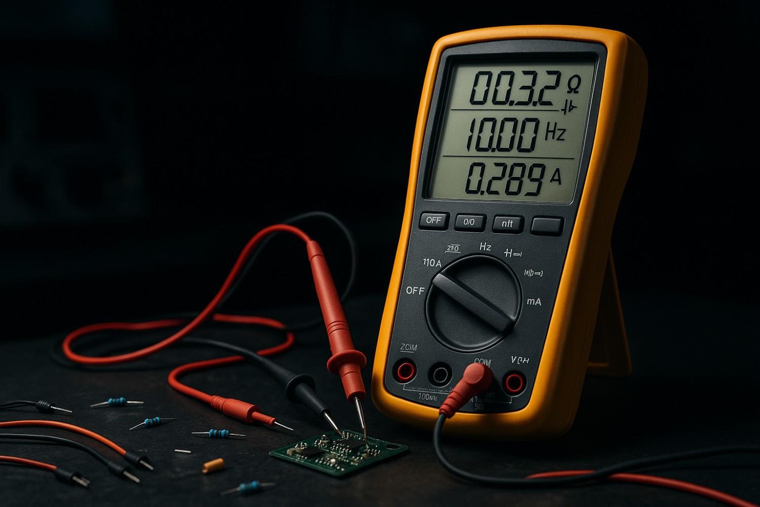
A Quick Tour of Your Fluke DMM
While models vary, most Fluke digital multimeters share a common anatomy.
- The Display: This is the screen where your measurement results are shown. It typically features four or more digits, a negative sign for polarity, and symbols that indicate the unit of measurement (e.g., V for Volts, Ω for Ohms, A for Amps).
- The Rotary Switch (Dial): This is the large knob in the center of the meter used to select the primary measurement function (e.g., AC Voltage, Resistance). On many Fluke meters, some positions on the dial have secondary functions printed in yellow. These are accessed by pressing the yellow "Function button" on the meter's face.
- The Ports (Jacks): These are the sockets where you plug in your test leads. Using the correct ports is critical for both safety and accuracy.
- COM (Common): This is the port for the black test lead. The black probe is connected here for all measurements, without exception.
- VΩmA (or similar): This is the primary port for the red test lead. It is used for measuring Voltage (V), Resistance (Ω), continuity, capacitance, and small currents (milliamps, mA).
- 10A: This is a special, high-current port used only for measuring currents greater than what the mA port can handle. Accidentally attempting to measure voltage with the red probe in this port will create a dangerous short circuit.
- The Probes (Leads): These are the insulated wires that connect the meter to the circuit. The red probe is for the positive connection, and the black probe is for the negative or common connection. Always hold the probes by their insulated handles, and never touch the exposed metal tips during a measurement.
The Golden Rules of Electrical Safety
Adhering to safety protocols is the most important skill you can learn. Most experts agree that you should always follow these rules:
- Inspect Your Gear: Before every use, visually inspect the multimeter, test leads, and probes for any signs of damage, such as cracks in the casing or frayed insulation on the wires. Do not use damaged equipment.
- Hands Off: Never touch the bare metal tips of the probes with your fingers when they are connected to a circuit.
- Proper Connection Sequence: When connecting to a live circuit, plug in and connect the black (COM) probe first, followed by the red (live) probe. When disconnecting, remove the probes in the reverse order: red first, then black.
- De-energize for Resistance/Continuity: Never attempt to measure resistance or continuity on a circuit that is powered. Always turn off the power and, if necessary, discharge any capacitors before testing.
- Measure Current in Series Only: Never connect a multimeter set to measure current in parallel with a power source (across the positive and negative terminals). This will create a short circuit, which can blow the meter's internal fuse or cause a dangerous arc flash.
Why CAT Ratings Are Your Most Important Safety Feature
A common point of confusion for beginners is the "CAT" rating printed on a multimeter. This rating is not about the maximum voltage the meter can measure; it is about the maximum transient (or spike) energy it can safely withstand in a given electrical environment. Using a meter with an inadequate CAT rating for the job is extremely dangerous.
A lightning strike or a large industrial motor switching off can create high-energy spikes that travel through power lines. A meter's CAT rating indicates its ability to survive such a spike without failing and endangering the user. The categories are based on your proximity to the power source.
|
Category |
Environment |
Typical Examples |
Potential Transient Danger |
|
CAT I |
Low-Energy Electronic |
Protected electronic circuits, signal-level circuits. |
Low |
|
CAT II |
Single-Phase Receptacle |
Household outlets, appliances, portable power tools. |
Medium |
|
CAT III |
Three-Phase Distribution |
Distribution panels, circuit breakers, fixed industrial equipment. |
High |
|
CAT IV |
Primary Supply (Utility) |
Outdoor lines, service entrance to a building, utility connection. |
Very High |
The key takeaway is to always match your meter's CAT rating to the environment. A meter with a higher CAT rating can be used in lower-category environments, but never the other way around. For example, a CAT III 600V meter is safer for working on a building's circuit breaker panel than a CAT II 1000V meter, because it is built to withstand higher energy transients, even though its voltage rating is lower.
Function 1: Resistance (Ω) – The Measure of Opposition
Beyond voltage, resistance is one of the most fundamental electrical properties you will measure.
What is Resistance? An Easy Analogy
Electrical resistance is the measure of an object's opposition to the flow of electric current. It is measured in units called Ohms, represented by the Greek letter omega (Ω).
A helpful way to understand resistance is the "water-and-pipe" analogy. Imagine electricity as water flowing through a pipe.
- Voltage is like the water pressure pushing the water.
- Current is like the flow rate of the water.
- Resistance is like a narrowing of the pipe or an obstruction inside it. The narrower the pipe (the higher the resistance), the harder it is for water to flow.
How to Measure Resistance Step-by-Step
Measuring resistance is straightforward, but it requires one critical safety step.
- SAFETY FIRST: You must never measure resistance on a circuit that has power. Always turn off the power source and de-energize the circuit completely before taking a measurement.
- Step 1: Turn the rotary switch on your multimeter to the resistance setting, marked with the omega symbol (Ω).
- Step 2: Ensure your probes are plugged into the correct ports: the black probe in COM and the red probe in the VΩ port.
- Step 3: Touch the tips of the probes firmly across the leads of the component you wish to measure. For measuring a single resistor, polarity does not matter.
- Step 4: Read the resistance value on the display. If the display shows "OL" (Overload), it means the resistance is either infinite (an open circuit) or higher than the range your meter is set to.
Real-World Use: Checking a Faulty Speaker or Resistor
- DIY Electronics: When building a project, you can use your multimeter to verify the value of a resistor to ensure you are using the correct one, rather than relying solely on its color code.
- Home Audio Repair: If a speaker stops working, you can test it. Disconnect the speaker wires and measure the resistance across its terminals. A good speaker will have a low resistance (e.g., 4 or 8 ohms). If the meter reads "OL," the voice coil inside is broken, and the speaker needs to be replaced.
Function 2: Continuity – Hearing the Connection
The continuity test is one of the most frequently used functions for quick troubleshooting.
What is Continuity? The Audible Path Finder
Continuity is the presence of a complete, unbroken path for current to flow. The continuity test on your multimeter is a quick check to determine if two points are electrically connected. The most useful feature is the audible beep. When the meter detects a complete path, it emits a sound, allowing you to test connections without looking at the screen.
How to Perform a Continuity Test
This test must also be performed on a de-energized circuit.
- SAFETY FIRST: Turn off all power to the circuit or component you are testing.
- Step 1: Turn the dial to the continuity symbol, which looks like a series of sound waves.
- Step 2: With the probes in the COM and VΩ jacks, touch the metal tips of the probes together. The meter should beep, confirming the function is working.
- Step 3: Place the probe tips on the two points you want to test (e.g., opposite ends of a wire).
- Step 4: A continuous beep signifies a complete path. No beep indicates the path is broken ("open" circuit).
Real-World Use: Diagnosing a Blown Car Fuse
If a component in your car, like the radio or headlights, suddenly stops working, the fuse is the first thing to check. Locate the fuse box, pull the relevant fuse out, and perform a continuity test across its two metal blades. If you hear a beep, the fuse is good. If there is no beep, the fuse has blown and needs to be replaced.
Function 3: Current (Amps) – Measuring the Flow
Measuring current is a powerful diagnostic function, but it is also the one that presents the most significant risk if done incorrectly.
Why Measuring Current is the Most Dangerous Function (And How to Do It Safely)
Current, measured in Amperes (A), is the rate at which electric charge flows. While voltage is measured across two points (in parallel), current must be measured by making the multimeter part of the circuit itself (in series).
To measure the flow of water in a pipe, you must cut the pipe and insert a flow meter into the line. The same is true for an ammeter. Attempting to measure current in parallel creates a short circuit, causing a massive surge of current that can blow the meter's fuse or cause a dangerous arc flash.
How to Measure DC Current Step-by-Step
Follow these steps precisely to measure DC current safely.
- Step 1: Turn off all power to the circuit.
- Step 2: Determine the expected current. If unsure, start with the highest setting. Plug the red probe into the 10A jack.
- Step 3: Turn the dial to the DC current setting, marked with an A and a straight line ($\text{A⎓}$).
- Step 4: Physically "break" the circuit where you want to measure, usually by disconnecting a wire.
- Step 5: Connect the multimeter in series. Touch one probe to the terminal and the other probe to the end of the wire you removed. The multimeter now bridges the gap.
- Step 6: Turn the power back on and read the measurement.
- Step 7: Once finished, turn the power off, disconnect the meter, reconnect the circuit, and immediately move the red probe back to the VΩ port.
Real-World Use: Finding a Parasitic Drain on Your Car Battery
If your car battery keeps dying, a "parasitic drain" may be the cause. With the ignition off, disconnect the negative battery terminal. Set your multimeter to measure DC amps (10A range). Connect the meter in series by placing one probe on the disconnected cable and the other on the negative battery post. The meter will display the current being drawn. A small draw (under 50 mA) is normal, but a higher reading indicates a problem.
Function 4: Capacitance (Farads) – Testing Energy Storage
Capacitors are fundamental components, and the ability to test them is a valuable skill.
What is a Capacitor? The Tiny Water Bucket Analogy
A capacitor stores electrical energy in an electric field, acting like a tiny, fast-acting rechargeable battery. Capacitance is measured in Farads (F). The "water bucket" analogy is excellent for understanding capacitors.
- Capacitance is like the size of a bucket.
- Voltage is like the water level in the bucket.
- Current is like the water flowing into or out of the bucket.
How to Measure Capacitance (Safely!)
- CRITICAL SAFETY STEP: Capacitors can store a dangerous charge long after power is off. You must always safely discharge a capacitor before testing it, typically by connecting a resistor across its terminals.
- Step 1: After discharging, remove the capacitor from the circuit for an accurate reading.
- Step 2: Turn the dial to the capacitance symbol (often looks like —|(—).
- Step 3: Insert the probes into the COM and VΩ jacks. Observe polarity if the capacitor has positive and negative leads.
- Step 4: Hold the probes on the terminals for a few seconds and read the capacitance on the display.
Real-World Use: Fixing an AC Unit's Failed Start Capacitor
A common failure point in home air conditioning (HVAC) units is the motor start capacitor. When it fails, the motor may hum but won't start. After safely de-energizing the unit and discharging the capacitor, you can test its capacitance. Compare the measured value to the rating printed on its side. If the reading is significantly lower, the capacitor is bad and needs to be replaced.
Function 5: Diode Test – The One-Way Street for Electrons
Diodes are the gatekeepers of electronics, and testing them is a fundamental troubleshooting step.
What is a Diode? An Electronic Check Valve
A diode is a semiconductor component that allows current to flow in only one direction, like an electronic one-way check valve.
How to Perform a Diode Test
- SAFETY FIRST: Perform this test on an unpowered circuit and discharge any capacitors.
- Step 1: Turn the dial to the diode test symbol (→|).
- Step 2: Connect the red probe to the anode and the black probe to the cathode (marked with a stripe). This is "forward bias".
- Step 3: A good silicon diode should display a small voltage drop, typically between 0.5 and 0.8 volts.
- Step 4: Reverse the probes ("reverse bias").
- Step 5: A good diode should now display "OL" (overload), indicating it is blocking current.
- Interpreting Faults: If the meter reads "OL" in both directions, the diode has failed open. If it shows a low voltage in both directions, it has failed short.
Real-World Use: Quickly Checking an LED
An LED (Light-Emitting Diode) is a special type of diode. You can use the diode test function to check if it's working. When you connect the probes in the forward-bias direction, a good LED will often glow faintly as the multimeter's test current passes through it.
Function 6: Frequency (Hz) – Measuring the Electrical Rhythm
While not used as often by hobbyists, the frequency function is a powerful diagnostic tool.
What is Frequency? The Pulse of AC Power
Frequency is the number of times an Alternating Current (AC) signal completes a full cycle in one second, measured in Hertz (Hz). The electricity in homes across India has a standard frequency of 50 Hz.
How to Measure Frequency
- Step 1: Turn the dial to the Hz setting. This may be a secondary function of the AC Voltage setting.
- Step 2: Ensure the probes are in the COM and VΩ jacks.
- Step 3: Carefully connect the probes across the AC source (e.g., a wall outlet).
- Step 4: Read the frequency in Hz. For a standard wall outlet, you should see a reading very close to 50 Hz.
Real-World Use: Checking a Portable Generator's Output
The frequency from a portable generator is tied to its engine speed. If the engine runs too fast or slow, its frequency will be off, which can damage sensitive electronics. By measuring the frequency of the generator's output, you can diagnose if its engine speed governor is working correctly.
Function 7: Temperature (°C/°F) – The Hidden Thermometer
Many professional-grade Fluke multimeters can double as a highly accurate digital thermometer.
How Thermocouples Unlock Temperature Readings
A thermocouple is a sensor used to measure temperature. Many Fluke DMMs can be equipped with a "K-type" thermocouple adapter and probe. The probe generates a tiny voltage that changes predictably with temperature, which the multimeter then converts into a precise temperature reading.
How to Measure Temperature
- Step 1: Plug the K-type thermocouple adapter into the COM and VΩ jacks, observing the correct polarity.
- Step 2: Turn the dial to the Temperature setting. This is often a secondary function activated by the yellow button.
- Step 3: Use a button to toggle between Celsius (°C) and Fahrenheit (°F) as needed.
- Step 4: Touch the tip of the thermocouple probe to the object you want to measure.
- Step 5: Allow a few moments for the reading to stabilize.
Real-World Use: HVAC and Automotive Diagnostics
- Home HVAC: Measure the air temperature coming directly out of a supply vent and compare it to the ambient room temperature to determine if your system is cooling or heating effectively.
- Automotive Diagnostics: A thermocouple can be used to precisely measure the temperature of fluids like coolant or to check components in the climate control system.
Conclusion: Go Beyond the Basics with Confidence
You have now moved beyond simple voltage checks and learned to use your Fluke digital multimeter as the powerful, multi-function diagnostic tool it was designed to be. By mastering resistance, continuity, current, capacitance, diode testing, frequency, and temperature measurements, you have dramatically expanded your ability to troubleshoot, repair, and build with confidence.
The key to continued success is practice. Start with safe, low-voltage projects to build your skills. Always prioritize safety, and never hesitate to review the fundamentals. As technology evolves, so do the tools we use. Check back with us for updates on the latest Fluke models and measurement techniques.
Ready to find the right tool for the job? Explore Revine Technologies' full range of genuine Fluke multimeters and accessories. Our expert application engineers are here to help you choose the perfect model for your needs.