Audio Equipment Testing: Using an Oscilloscope to Test Amplifiers
Audio amplifiers are at the core of sound systems used in consumer electronics, professional audio, automotive systems, and industrial applications. When an amplifier underperforms, distorts audio, or fails under load, software-based checks are not enough. The behavior of the electrical signal itself must be analyzed.
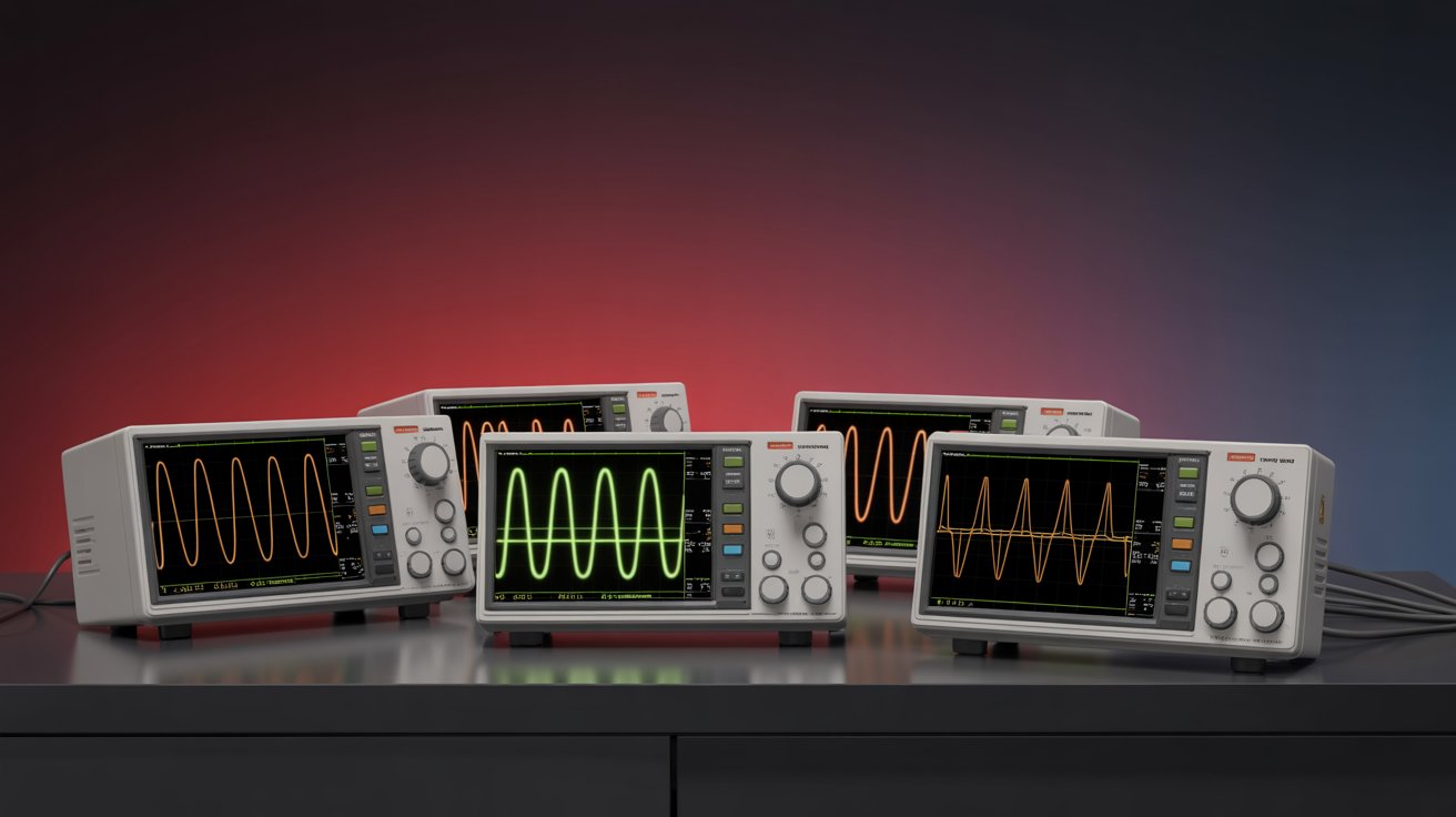
An oscilloscope is one of the most effective tools for audio equipment testing. It allows engineers and technicians to visualize waveforms, identify distortion, measure gain, and verify stability. This article explains how to test amplifier performance using an oscilloscope, step by step, with a focus on practical audio testing workflows.
Why Use an Oscilloscope for Audio Amplifier Testing
Audio amplifiers process analog signals that change continuously with time. Small issues such as clipping, noise, oscillation, or power rail instability can significantly affect sound quality.
Using an oscilloscope helps you:
- Visualize input and output waveforms in real time
- Detect clipping, crossover distortion, and saturation
- Measure amplifier gain and frequency response
- Identify noise, hum, and unwanted oscillations
- Validate performance under different load conditions
For anyone working with Oscilloscopes in audio or electronics labs, this visibility is essential for accurate troubleshooting and validation.
Basic Test Setup for Audio Amplifier Measurements
Required Equipment
- Oscilloscope with sufficient bandwidth for audio signals
- Signal source such as a function generator or audio source
- Amplifier under test
- Dummy load or speaker load
- Proper measurement probes
Function Generators are commonly used to inject clean sine waves for controlled audio testing.
Probe and Connection Guidelines
- Connect the oscilloscope ground to the amplifier ground reference
- Use one channel for the input signal and another for the output
- Set probe attenuation correctly (typically 10×)
- Avoid long ground leads to reduce noise pickup
Improper probing can introduce measurement errors, especially in low-level audio signals.
Step-by-Step: Testing an Amplifier with an Oscilloscope
Step 1: Verify the Input Signal
Start by checking the input signal before it enters the amplifier.
What to observe:
- Clean sine wave shape
- Correct frequency (commonly 1 kHz for testing)
- Stable amplitude
This ensures the signal source is not contributing distortion. Pairing an oscilloscope with Digital Multimeters can help confirm RMS voltage levels.
Step 2: Measure Output Waveform and Gain
Compare the amplifier output waveform to the input.
Key checks:
- Output waveform shape matches input
- No flattening or clipping at normal levels
- Expected voltage gain is achieved
Gain can be calculated directly by comparing peak-to-peak voltages on the oscilloscope.
Step 3: Detect Clipping and Distortion
Increase the input level gradually while observing the output.
Signs of distortion include:
- Flattened waveform peaks (clipping)
- Asymmetry between positive and negative halves
- Irregular waveform shape
Clipping indicates the amplifier is reaching its voltage or current limits, often due to insufficient Power Supplies or incorrect load impedance.
Step 4: Check Frequency Response
Sweep the input frequency across the audio range, typically from 20 Hz to 20 kHz.
Using an oscilloscope, observe:
- Amplitude consistency across frequencies
- Phase shift at low and high frequencies
- Any unexpected roll-off
This test reveals bandwidth limitations and coupling capacitor issues.
Step 5: Analyze Noise and Hum
With no input signal applied, observe the output waveform.
Common issues visible on an oscilloscope:
- 50/60 Hz hum from power supply ripple
- High-frequency noise from poor grounding
- Random noise due to component issues
Spectrum Analyzers are often used alongside oscilloscopes for deeper noise and frequency-domain analysis.
Common Amplifier Issues Visible on an Oscilloscope
|
Issue |
Observed Waveform |
Typical Cause |
|
Clipping |
Flattened peaks |
Insufficient supply voltage |
|
Crossover distortion |
Notch near zero crossing |
Improper biasing |
|
Oscillation |
High-frequency waveform |
Stability or layout issues |
|
Power ripple |
Low-frequency modulation |
Poor filtering |
Recognizing these patterns helps speed up fault isolation during audio testing.
Testing Amplifiers Under Load
Testing without a load does not reflect real-world operation.
Best practices:
- Use a resistive dummy load matching speaker impedance
- Monitor waveform changes under load
- Check for thermal drift over time
This approach aligns with professional validation and QA workflows in audio electronics.
Practical Lab Tips for Audio Testing
- Always begin with low signal levels
- Use proper shielding and grounding
- Save waveform captures for documentation
- Verify measurements using multiple instruments
- Combine oscilloscope testing with Probes designed for low-noise analog signals
These habits improve repeatability and accuracy in audio equipment testing.
When Additional Instruments Are Needed
An oscilloscope provides time-domain insight, but complete audio analysis may require more tools.
Engineers often combine it with:
- Function Generators for precise test tones
- Spectrum Analyzers for harmonic distortion analysis
- Data Acquisition Systems for long-term measurements
- Embedded Tools when testing digital audio control circuits
Using the right tool set ensures reliable amplifier performance evaluation.
Conclusion
Using an oscilloscope to test amplifiers provides direct insight into signal quality, distortion, and stability. By observing real waveforms instead of relying on subjective listening alone, engineers and technicians can identify hardware issues early and validate amplifier designs with confidence.
Whether you are troubleshooting a faulty audio amplifier or validating a new design, oscilloscope-based audio testing is a fundamental skill in electronics and test and measurement engineering.
FAQ
What frequency is commonly used to test audio amplifiers?
A 1 kHz sine wave is widely used as a standard reference for amplifier testing.
Can an oscilloscope measure audio distortion accurately?
It can visually reveal distortion, clipping, and noise, but quantitative THD measurements usually require a spectrum analyzer.
Is a high-bandwidth oscilloscope necessary for audio testing?
Audio signals are low frequency, but higher bandwidth helps detect oscillations and high-frequency instability.
Why does an amplifier clip even at low volume?
Possible causes include incorrect biasing, insufficient supply voltage, or an improper load.
Should amplifiers always be tested under load?
Yes. Testing with a proper load reveals behavior that may not appear under no-load conditions.